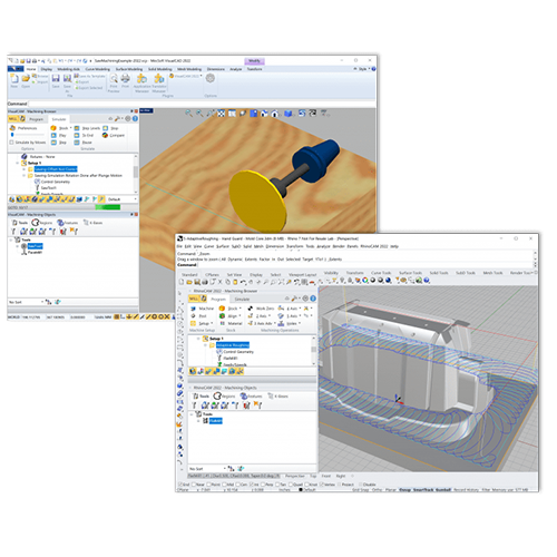
Indexed 5 Axis Machining in VisualCAMc

Add Your Heading Text Here

There is a class of components that cannot be machined using standard 2-Axis and 3-Axis toolpath methods alone. For example, the component might have a negative draft that the cutting tool cannot reach using a 3-Axis toolpath method, or it may have a group of machinable features that are simply not oriented for direct access by a 3-Axis machine tool.
These classes of components require a method referred to as “indexed machining.” The automotive industry is a primary example of where indexed machining methods are widely employed. In this blog, we’ll discuss how you can perform indexed 5-Axis machining using VisualCAMc, the production CAM solution for Onshape. Let’s look at a sample automotive component and explore how to setup VisualCAMc for performing indexed 5-Axis machining.

5-Axis Terminology

Before we get started, let’s discuss some 5-Axis machining terminology that will help you understand the process. To perform indexed machining, you first need to have a machine tool capable of indexing (locking) its orientation in one or more of the three principal axes (X,Y or Z).
A 5-Axis CNC machine is capable of both indexed and continuous machining. In the case of indexed machining, the rotary axis is locked to a given orientation while machining is performed. The rotary axis can then be indexed (reoriented) to perform machining in other areas. 5-Axis indexed machining is also known as (3+2) machining, where you lock the tool axis to any given plane (orientation) and then program 2-Axis and 3-Axis toolpath operations.

VisualCAMc supports the three configurations commonly found on 5-Axis machine tools:

  • 5-Axis Head-Head Configuration
    This type is common when machining large parts where both the rotational axis is on the spindle head and the part remains stationary on the machine table (i.e., the part does not rotate). This article illustrates a 5-Axis Head – Head configuration.
  • 5-Axis Table-Head Configuration
    One rotary axis is on the table where the part rotates, and the other rotary axis is on the spindle.
  • 5-Axis Table-Table Configuration
    Both rotary axes are on the table where the part rotates to different orientations. This is also known as a Trunnion.

The 5-Axis Part

The Onshape part chosen for this blog is a 12-cylinder engine block assembly. We will discuss the setup of the 5-Axis machine tool definition, including two setups and three toolpath operations each for both sets of cylinders shown in the engine block below. Notice the location of the World Coordinate System (WCS) Origin in the Onshape part Document.

The 5-Axis Machine Definition

When you open a new VisualCAMc tab and load a part from an Onshape Document, the Machine definition in the Machining Job defaults to a 3-Axis machine. The first and most important task in your indexed 5-Axis project is to properly set the Machine definition according to the specifications of YOUR MACHINE TOOL. You will need to know the spindle head configuration as well as the primary and secondary axis specifications. In this blog, we will set the Machine definition to a typical 5-Axis machine and explain the key parameters that you will need to understand.

You can select Machine from the VisualCAMc Mill tab or double-left-click on Machine located under the Machining Job. These locations are shown below.

The Machine Coordinate System

This will display the Machine dialog, which contains two tabs, Machine Coordinate System and Machine Definition. In our example, the Machine Coordinate System (MCS) is aligned with the World Coordinate System (WCS) in the Onshape Document. From the Machine Coordinate System tab, you can select the Align to World Coordinate System button to set this. By default, the MCS Origin is also located at the WCS Origin. You can verify this if you see “X: 0.0Y: 0.0 and Z: 0.0” in the Coordinate System Origin fields at the bottom of this tab as shown below.
Mach Dialog: Machine Coordinate System tab

The Machine Type

Now let’s move to the Machine Definition tab. First, we’ll set the Machine Type by setting the Number of Axes to 5-Axis and the Configuration to Head-Head. This means that the 4th and 5th axis rotations of the machine are contained within the spindle head. The image below shows a typical 5-Axis Head-Head spindle configuration.
Mach Dialog: Machine Definition tab
A Typical 5 Axis Head – Head Spindle Configuration

The 4th and 5th Axis Parameters

With the Machine Type set to 5-Axis, you can see that the additional 4th and 5th axis parameters are activated within the dialog. Under the 4th Axis (Primary Axis) Parameters, you will see sections for the Rotary Axis and the Rotary Center. It is critical that you get the Rotary Axis selection correct for your 5-Axis machine. In our 5-Axis Head-Head configuration, the 4th Primary Axis is in the +Z direction. You can refer to the illustration below for how the 4th and 5th axis are configured for this example. Moving down to the 5th Axis (Secondary Axis) Parameters section of the dialog, we have the Rotary Axis set to +Y.

You will also notice that the 4th and 5th Rotary Axis sections of the dialog have an Angle Limit selector. This needs to match the angle limits of YOUR 5-Axis machine tool. We have our 4th Axis set to “No Limit” and our 5th Axis set to “User Defined Limits” – and have Min set to -120 and Max set to 120. So our 5th Axis is limited to +/-120 degrees. Again, the values you use should match your machine tool specifications.

Add Your Heading Text Here

Lorem ipsum dolor sit amet, consectetur adipiscing elit. Ut elit tellus, luctus nec ullamcorper mattis, pulvinar dapibus leo.

Mach Dialog: Machine Definition tab, 4th & 5th Axis Parameters
Our 5 Axis Head – Head Spindle

The Spindle Head Gage Length

You will notice an additional parameter called “Gage Length.” This parameter is active when the configuration involves a Head and when “Output all coordinates in local setup coordinate system” is not checked. This checkbox is located in the General Parameters section of the dialog. Because our 5-Axis machine has a rotary head (i.e., Head-Head configuration) and we are outputting World coordinates, we need to specify this parameter value. Gage Length is the fixed distance between the pivot point and the spindle face (see the illustration above).

The Rotary Axis Codes

You may be asking yourself, “Why are the primary and secondary axes labeled B and C in the illustration above?” The reason is that all 5-Axis machine controllers have a code for each axis. Typically, these are designated as XYZ and ABC (X=A, Y=B and Z=C). So in our 5-Axis machine configuration example, we have the 4th Primary Axis set to +Z (this is the C Axis) and the 5th Secondary Axis set to +Y (this is the B Axis). Since these axis codes can change for different 5-Axis machine controllers, they are configured within each post-processor. You will see these rotary axis codes when we post the 5-Axis G-Code below.

The 5-Axis Post Processor

VisualCAMc supplies over 300 default post processors configured for different CNC machine controllers. However, none are set up for 5-Axis machining by default. We want to make sure that the post YOU use is set up correctly for YOUR 5-Axis machine tool. If you need a 5-Axis post, please contact us directly at support@mecsoft.com with your machine type, controller type and sample G-Code files that your machine reads. We will then supply you with a post-processor that is configured specifically for your machine controller. In this blog, we are using a Mach3-INCH post-processor configured for 5-Axis G-Code output that matches the machine definition we have discussed above.

The 5-Axis Setups

In VisualCAMc, a 5-Axis setup is created in the same way a 3-Axis or 4-Axis setup is created by using the Setup dialog whose command is located on the Mill tab of the VisualCAMc toolbar. The only difference is the setup’s XYZ Axis orientation. The key word here is orientation. We are referring to the angular orientation of each axis. In a 3-Axis setup, the X and Y Axis are fixed in the same orientation as the 3-Axis Machine Definition (i.e., each is locked at zero degrees). In a 4-Axis setup, the 4th primary axis (i.e., the radial axis) can rotate subject to the limits set by the Machine Definition. In a 5-Axis setup, an additional 5th secondary axis can also rotate, again subject to the limits set by the Machine Definition.

In the illustrations below, you can see the XYZ Axis orientations for this sample part. On the left image, we see the default orientation of the Machine. Each axis is at zero degrees. In the middle image, we see the axis orientations for Setup 1 (Side A). You will notice that the Y Axis is indexed to +30 degrees. In the right image, we see the axis orientations for Setup 2 (Side B). You will notice here that the Y Axis is indexed to -30 degrees.

The 2½-Axis Machining Operations

The machining operations in this example include 2½-Axis Facing, 2½-Axis Hole Pocketing and a Bore Hole Making operation. While we will not go into the cutting parameters of each of these operations, it is important to note that each appears under Step 1 (Side A) and Setup 2 (Side B). Each operation is illustrated in the images below. Again, the only difference in these two setups is the angle orientation (i.e., rotation) of the Y Axis. In Setup 1 (Side A), the Y Axis is set to +30 degrees. In Setup 2 (Side B), the Y Axis is set to -30 degrees. When this set of 2½ Axis operations appears under either setup, they are subject to the indexed XYZ Axis orientation of that setup.

Posting 5-Axis G-Code

When post-processing toolpath operations in a 5-Axis Machine definition, it is important to remember that the axis orientations are defined in each Setup definition. This means that if you want to include the axis angle codes in the posted G-Code file, you must include a Setup in your selection when you right-click and select “Post-Process.” Here are some example G-Code results depending on different selections from the Machine Job tree.

Posting the Machining Job

If you ONLY select the top-level Machining Job folder and then Post-Process, you will get the following G-Code: Setup 1, its primary and secondary axis codes and angles, followed by the G-Code required for each operation under Setup 1 (Side A). This is followed by Setup 2 (Side B), its primary and secondary axis codes and angles, and the G-Code required for each operation under Setup 2 (Side B).
Machining Job Tree
Posted G-Code File

Posting a Setup

If you select Setup 2 (Side B), right-click and select Post-Process, you will get the following G-Code: It will include the primary and secondary axis codes and angles for Setup 2 (Side B), followed by the G-Code required for each operation under Setup 2. Notice that the first operation in the G-Code file is (Cyl Face (Side B)). That is the first operation that appears under Setup 2 (Side B) in the Machining Job.
Machining Job Tree
Posted G-Code File

Posting a Setup and Operation

If you press the <Ctrl> key and then select Setup 2, as well as the second operation Cyl Hole Pocket (Side B), and then Post-Process, you will get the following G-Code: Notice that the primary and secondary axis codes and angles for Setup 2 (Side B) are included and is followed by the G-Code for Cyl Hole Pocket (Side B).
Machining Job Tree
Posted G-Code File

Posting Only an Operation

If you ONLY select one operation such as the Cyl Bore (Side B) and then Post-Process, you will get the following G-Code: No Setup 2 primary and secondary angle codes and angles are included. Only the G-Code required for Cyl Bore (Side B) is included in the G-Code file.
Machining Job Tree
Posted G-Code File

Let’s Review

Using VisualCAMc for Onshape, you can program toolpaths and post them for indexed 5-Axis output that is tailored to your specific machine tool! Here are the key things to remember so that you can quickly join the ranks of other successful VisualCAMc users:

  • The 5-Axis Machine Definition: This is the most critical step of any 5-Axis project. Make sure you have the correct machine configuration selected and that the 4th Primary Axis and 5th Secondary Axis as well as the Angle Limits for each is set correctly to match YOUR machine tool.
  • The 5-Axis Post Processor: Make sure you are using a post-processor that has been configured for 5-Axis output and that it is configured correctly for your machine tool’s axis codes. If you need a 5-Axis post please contact us directly at support@mecsoft.com with your machine type, controller type and sample G-Code files that your machine reads. We will then supply you with a post-processor that is configured specifically for your machine controller.
  • The 5-Axis Setups: Just make sure the setup orientation is correct for the part features you want to machine. The +Z Axis of the setup should point normal to the spindle face. The Setup dialog contains the controls you need to properly orient your setup.
  • The Toolpath Operations: Create the required 2-Axis, 3-Axis and/or Hole Making operations as needed based on your part feature requirements and with your machine tool’s operation specifications.
  • The 5-Axis G-Code: Check your resulting G-Code files to make sure the proper axis codes and angles are being posted. You can perform a “dry-run” of a simple indexed 5-Axis G-Code program (with no workpiece) on your machine tool to check for axis orientations and possible controller alerts. You can make the needed adjustments.

Try It Yourself

If you want to learn more about the VisualCAMc Milling plugin for Onshape, check out MecSoft’s Products Page, and our YouTube Channel for what’s new, specifications, videos, tutorials and more. To get VisualCAMc, go to the Onshape App store and add VisualCAMc to your Onshape account. Enjoy!
Powerful 2-5 axis machining capability for Onshape!
Don LaCourse

Don LaCourse

Don LaCourse is an Application Engineer with MecSoft Corporation. Don brings over 20 years of experience in CAD/CAM operations in both automotive and mold design applications. Don also has extensive experience in documenting CAD/CAM products and is actively involved with writing the on-line help as well as creating training tutorials for MecSoft's products.
Shopping Cart