As a rule undercuts are to be avoided when designing part features as well as the injection mold cavities. If undercuts are present when the cavity is injected with hard plastics such as Acetal and ABF “mold-lock” condition occurs, not allowing the cavities to be separated without destroying the injected part.
However, there is a group of components in which the machining undercuts in mold cavities is required. Such components include Keypads, Gaskets, Seals, Hand Grips, O-rings, Rollers and Washers. These types of components are typically injected with silicone or rubber compounds, allowing mold cavity separation without damage to either the part or the cavity.
The following quad-ring seal injection mold cavity inserts, used in irrigation and hydraulic applications, were submitted by Casie Simmons Lead Machinist for Lane Manufacturing. It illustrates the use of 2½ Axis Profiling toolpath operations in VisualCAD/CAM for undercutting mold cavities.
The VisualCAM Part
The parts selected for this case study are a set of cavity inserts for a 3-plate mold for injection molding 8 quad-ring seals at a time. The seals are used in irrigation and hydraulic applications. The resulting seals are approximately 5” in diameter and ½” thick with one half of the seal being molded by each cavity. The cross-sections and dimensions below illustrate the complexity of these cavities.
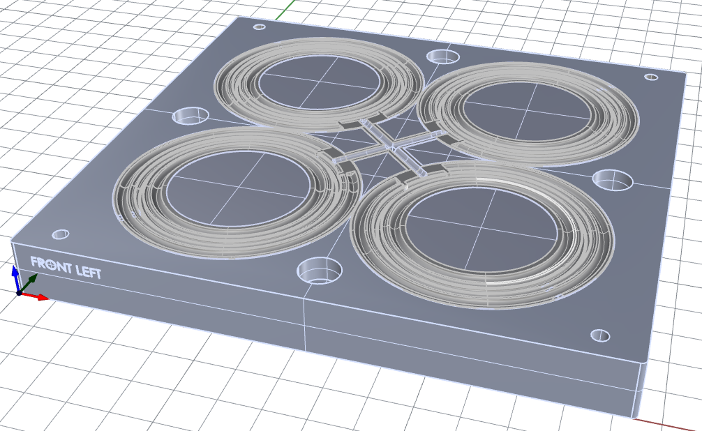
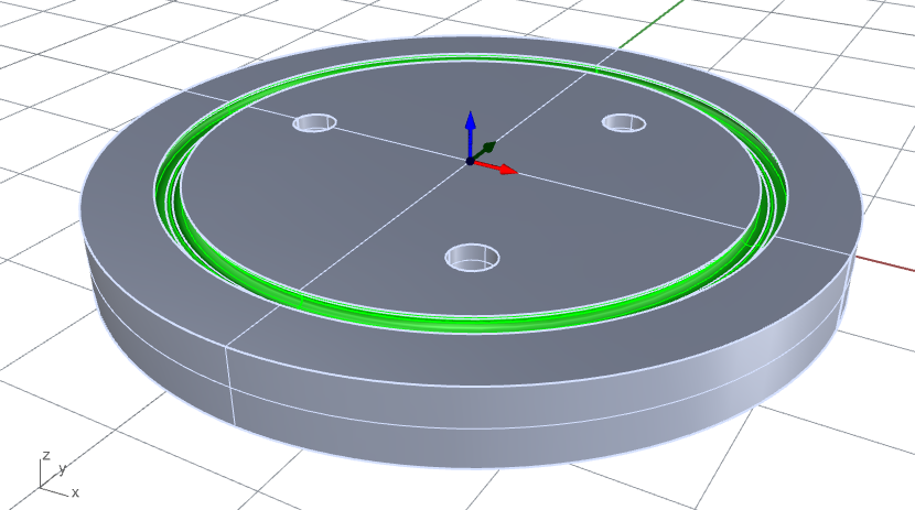


Here we see the cross-sections of the quad-ring seal cavity inserts. This machining job requires some very precise cutting paths to reproduce these undercut cavities as mentioned above.
The Cutting Tool
The cutting tool used for this machining job is a 2-flute CARBIDE ball undercutting end mill with a ball diameter of 0.0938”, a shank diameter of 0.038” and a shoulder diameter of 0.125. The Cutting Tool and the Tool definition dialog are shown below.


The Machining Job
The undercut constraints of the quad-ring cavity requires a specific type of tool, This being a 2-flute CARBIDE ball undercutting end mill with a ball diameter of 0.0938” and a shank diameter of 0.038”. You can refer to the tool images above for details. The Cutting Tool necessitates the use of multiple (over 50) 2-Axis Profiling operations each with a small amount of material removal. Samples of the Machining Job tree are shown below.
On the left you see the entire Machining Job starting with a 3 Axis Horizontal Roughing operation named “ROUGH O’RING GROOVE” that is followed by 6 Machining Operation Sets (referred to as MOpSets). Each MOpSet contains 10 or more 2½ Axis Profiling operations.


The Machining Job trees shown above show the depth of the machining operations required to cut these quad-ring seal grooves into each cavity. Each operation removes a small amount of material due to the size of the 0.0938” cutting diameter.
2½ Axis Profiling (64 Operations)
Because of the size of the cutting tool and the shape of the quad-ring seal cavity, only a small amount of material can be removed at a time. Because of this, a total of (64) 2½ Axis Profiling operations are required, each one precisely positioned to remove one level of stock material resulting in the undercut cavity. Below is the first 2½ Axis Profiling operation in the Machining Job. The remaining 63 operations are very similar except for the location of the control geometry and the depth of cut.

The Cut Parameters tab of the first of (64) 2½ Axis Profiling toolpath operations is shown above. Note that the Global Tolerance is set to 0.0001” and the Cut Direction is set to Climb (up cut).

The Cut Levels tab of the first of (64) 2½ Axis Profiling toolpath operations is shown above. Note that the Total Cut Depth is set to 0.0469” inches. This operation is shown in the cross-section illustration below.

A Note About the Arc Fitting Tolerance
When Perform Arc Fitting is enabled, consecutive linear motions (G01s) are converted to circular arc motions (G02s and/or G03s). The Fitting Tolerance should be 2 times the Global Tolerance set on the Cut Parameters tab. This allows the CAM program to locate the next G01 coordinate in the fitted arc. If you feel the Fitting Tolerance is too high for your needs, then set the Fitting Tolerance to your final required tolerance and then set the Global Tolerance to 0.5 times your Fitting Tolerance.
Accuracy & Precision
MecSoft’s CAM solutions like VisualCAD/CAM and RhinoCAM allow users to “dial-in” the exact amount of precision needed for each job. Whether engraving signs or machining production mold cavities, our CAM software by default operates with an internal precision of 14 decimal places. Users can then, using controls offered in the software, calibrate the exact precision required for a specific machine tool or a job, during the creation of toolpaths as well as during post-processing.

Above we see the cross-section of the Quad-Ring seal cavity during the first of (64) 2½ Axis Profiling operations. The cavity profile is shown in red and the control geometry for the Profiling operation is shown in blue. Note that cutting is being performed on the right side of the 2-flute CARBIDE ball undercutting end mill. Also note that a 3 Axis Horizontal Roughing operation is first performed to remove material from the cavity.
The Cut Material Simulation
The cut material simulation video for the above Machining Job can be watched below. It is accelerated so you can see the entire cavity being cut.

Project Wrap
The image below shows a proof-of-concept cavity plate and a prototype quad-ring seal. We want to extend a special thanks to Casey Simmons and Lane Manufacturing for allowing us to showcase their work.


More about Lane Manufacturing
Lane Manufacturing strives to provide the best quality product and unmatched customer service. With over 50 years in the industry they have an unmatched sample inventory and reference library of irrigation gaskets. With in-house design and mold fabrication they have turned around production products in days instead of the weeks or months it can take others.


You can reach out to Lane Manufacturing via the channels below:
Add Your Heading Text Here
Lorem ipsum dolor sit amet, consectetur adipiscing elit. Ut elit tellus, luctus nec ullamcorper mattis, pulvinar dapibus leo.


Add Your Heading Text Here
Lorem ipsum dolor sit amet, consectetur adipiscing elit. Ut elit tellus, luctus nec ullamcorper mattis, pulvinar dapibus leo.


