Toolpath Strategy for 3D Contoured Grooves

Search

Blog Categories

Below is an illustration of a guitar body with features such as holes, pockets, grooves, and sculpted surfaces. Part features can be found on both sides (Top and Bottom).  We will discuss how best to toolpath the 3D contoured groove feature in this guitar body. We will use a project by Jeff Kosmoski of KOZM Guitars as the perfect example.
The 3D model of the guitar body is shown.

The 3D Contoured Groove Geometry

The 3D Contoured Groove feature traverses the entire length of the guitar body following a contoured path. The groove has constant dimensions of 0.145” wide and 0.133” deep. This means that the depth of the groove is measured from the contoured top surface of the guitar body. Also, because the top of the guitar body is not flat, the groove changes in elevation as it travels. The illustration below shows the start and end of the 3D Contoured Groove.
The guitar body has a 3D Contoured Groove that runs the length of the part from right to left. The yellow circle on the right shows where the groove enters and the red circle on the left shows where the groove exits the guitar body.

Creating the Spine Curve

The 3D Contoured Groove is best programmed by defining the Spine Curve.  The Spine Curve is located at the bottom center of the groove. The Spine Curve is created from the surface edges located at the bottom of the groove. The following steps are performed. Also, refer to the illustration below.

  1. 3D Curves are created from the surfaces located on the side wall of the groove.  More specifically, new curves are created from all edges located at one side and at the bottom of the groove.
  2. These curves are then merged to form one curve that runs the entire length of the groove at its base on one side.
  3. The 3D curve is then offset inward, toward the center of the groove, by 0.0725″ which is exactly one-half of 0.145”, the actual width of the groove.  This becomes the Spine Curve.
  4. The new offset curve is positioned at the mid-way of the groove and at the bottom.  We are calling this the Spine Curve shown in red in the illustration below. 
The 3D Contoured Groove is a part feature. The Spine Curve is shown in red.

Creating the 2½ Axis Engraving Operation

A 2½ Axis Engraving toolpath operation is performed on the 3D Contoured Groove spine curve using a 0.145” diameter flat-end mill.  The center flat tip of the end mill follows the spine curve through 3-dimensional space starting at the beginning of the spine curve all the way to the end of the spine curve.
The Cutting Parameters include a global tolerance of 0.001”.  The location of Cut Geometry (i.e., the spine curve) is set to At Bottom.  This is the bottom of the cut.  The Cut Depth, Rough Depth, Finish Depth, Rough Depth/Cut, and Finish Depth/Cut are all set to zero.  This means that the cutter will follow the spine curve and not cut any deeper than that.  The Cut Parameters tab of the Engraving operation is shown below.
Here is the 2½ Axis Engraving Operation Cut Parameters tab.

Engraving Toolpath Entry and Exit Parameters

Controlling how the flat-end mill cutter enters and exits at the spine curve is of particular importance.  The Entry and Exit of the flat-end mill must remain normal to the direction of the spine curve in order to remain dimensionally accurate to the 3D Groove.

For display and illustration purposes, we see that any toolpath is divided into the following 7 segments; Plunge, Approach, Engage, Cut Motion, Retract, Departure, and Rapid.  The motions that will control how the flat end mill enters and exits the 3D Contoured Groove are the Approach, Engage at the start of the groove, and the Retract and Departure at the end of the groove.  The default Toolpath Colors are shown in the Toolpath tab of the CAM Preferences dialog.
Toolpath Segments and Colors

Engraving Toolpath Entry Parameters

The dialog below is the Entry Motion portion on the Entry/Exit tab of the Engraving operation dialog.  The Entry Motions are adjusted so that the toolpath will Plunge vertically (from outside the groove) to the Approach Motion Vertical Distance.  It will then begin a 0.5” Linear Engage motion that ends at the start point of the Spine Curve.  The Cut Motion then begins at the start of the Spine Curve.
2½ Axis Engraving toolpath operation Entry Motion Parameters
2½ Axis Engraving toolpath operation Entry Motion Illustrated

Engraving Toolpath Exit Parameters

The dialog below is the Exit Motion portion on the Entry/Exit tab of the Engraving operation dialog. The Exit Motions are adjusted so that the Cut Motion stops at the end point of the Spine Curve. The cutting tool then retracts a Linear distance of 0.5”. At this point the toolpath rapids vertically to the clearance plane.
2½ Axis Engraving toolpath operation Exit Motion Parameters
2½ Axis Engraving toolpath operation Exit Motion Illustrated

Controlling the Entry and Exit Angles

The Entry and Exit Angles refer to the elevation of both the Engage and the Retract segments of the toolpath. In this case, we want the cutting tool to remain tangent to the Spine Curve to achieve a smooth entry and exit of the groove. In the Entry/Exit dialogs shown above you will see a parameter named Angle (A). This is the angle at which the Engage and the Retract segments connect to the Spine Curve. In both cases, Angle (A) is set to 0 (zero). This keeps the Engage and the Retract segments tangent to the Spine Curve.
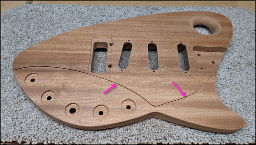
Here we see the end result of machining the 3D Groove using the 2½ Axis Engraving method.

About Jeff Kosmoski

Jeff Komoski is a Mechanical Engineer who has used various CAD packages in his day jobs since the early 80s. These have included Unigraphics, CADKEY, ProE / Creo, Solidworks, and most recently, NX. Jeff currently works for ThermoFisher Scientific, working on electron microscopes and ion-generating columns. Jeff also has experience in numerous product arenas including Aerospace, Medical, Robotics, Color Printers, Scientific Instruments as well as Consumer Products.

Cool Designs from KOZM Guitars!

More about KOZM Guitars

You can learn more about Jeff Kosmoski and KOZM Guitars by visiting his website at www.kozmguitars.com. To learn more about Jeff’s CNC process you can visit the Digital Lutherie page. We want to extend a special thanks to Jeff Kosmoski for allowing us to showcase his work!
Cool project Jeff!
Thank you for allowing us to showcase your work!

From the blog

The latest industry news, interviews, technologies, and resources.
Don LaCourse

Don LaCourse

Don LaCourse is an Application Engineer with MecSoft Corporation. Don brings over 20 years of experience in CAD/CAM operations in both automotive and mold design applications. Don also has extensive experience in documenting CAD/CAM products and is actively involved with writing the on-line help as well as creating training tutorials for MecSoft's products.

Try us out,

no strings attached!

Download Demo Form

Name(Required)
Product of Interest(Required)
This field is for validation purposes and should be left unchanged.

Name(Required)
Product of Interest(Required)
This field is for validation purposes and should be left unchanged.