Cool Machining Job from Technology Patent

Search

Blog Categories

Gordon Marsh is an Entrepreneur and inventor living in Wetumpka Alabama. Gordon, along with his two sons, owns several companies including Blue Line Arsenal where he manufactures automatic weapons for law enforcement, and Green Fuel, LLC

Gordon currently owns a patent on a machine that makes hydrogen from distilled water and sunshine! You heard that correctly. Gordon is producing Hydrogen fuel from distilled water and sunshine, at pressures of up to 5,000 PSI, but without a compressor!  The part and machining job illustrated below is a prototype component in Gordon’s patent.

The VisualCAD/CAM Part

The part Gordon has chosen for this case study is shown below. It requires both 2½ Axis and 3 Axis CAM strategies. It is also a multi-sided part, meaning that it requires machining from multiple sides. In this case study, we only discuss the machining required for the top side.
Here we see the component features on the top side (Left) and the bottom side (Right).
Here we see a cross-section view of the component.

The Machining Job

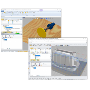
In Setup 1, the top side of the component is machined. The VisualCAD/CAM Machining Job tree is also shown here. The machining operations in this setup include Drilling, 2½ Axis Pocketing, 2½ Axis Facing, and 2½ Profiling. Also included are 3 Axis Roughing and 3 Axis Finishing. Each of these machining operations is discussed in detail below. Beginning from the top of the Machining Job we see that it consists of a 3 Axis Machine definition.

Post Definition​

We also see the Post-processor used for this Setup is CNCMasters-Inch-2. This means that all of the G-Code files produced from this setup will be tailored for Gordon’s CNC Masters 3 Axis Machining Center.

Stock Definition

Next in the Machining Job, we see that the Stock is defined as a Box Stock. The Stock dimensions are 5.01” long, 3.01” wide, and 1.625” tall and the stock material is 1010 Steel.

Fixture Definition

After the Stock, we see that Fixtures are set to None, meaning that no Fixtures are defined in the setup. However, Gordon will be clamping the stock to his machine table. Since we are not machining all the way down around the sides of the stock, the actual clamping fixtures do not need to be displayed or defined. In the last 2½ Axis Profiling operation illustrated below you will see that the cutting stops 0.625” from the CNC table.

The Work Zero

In this setup Gordon will be homing his CNC machine to the top of the stock and in the northeast corner so the Work Zero is located there. The Work Zero is represented on the screen graphically by the Blue, Red, and Green triad. This location will be the origin of the Machine Coordinate System, also referred to as the MCS origin.

Center Drill (⅛” Holes)

Setup 1 starts out with a Center drill, also referred to as a Spot Drill operation, located at the 10 drilled holes as well as the center of the two contoured circle pockets. The drill used is a 1/8” diameter, 0.25” flute length center drill. Cut parameters include a Cut Depth of 0.125” and the hole will start at the top of the stock which is 0.0625” above the part.

Deep Drill (¼” Holes)

Next up is a Deep Drill operation. This will drill the 10-hole pattern as well as two holes at the center of the two contoured circular pockets. These two holes will provide ease of access for the upcoming 3 Axis roughing operations in these two pockets. The tool used is a ¼” diameter drill. The drilling parameters include a total cut depth of 1”. Being a Deep Drill operation, each hole will incorporate step increments of 0.1”. The drill will retract from the hole after each 0.1” increment clearing the hole of cut material.

3 Axis Horizontal Roughing

With the drilling out of the way, we can start the roughing operations on the two contoured circular pockets. The operation employs a ½” diameter end mill. Cut parameters include a roughing tolerance of 0.01” and a stock allowance of 0.025”. The end mill cutter will stay 0.025” away from all part surfaces during the cut. It also employs an Offset Cut Pattern and a Mixed Cut Direction/ It will start at the center of the pocket and cut outward with a Stepover of 25% of the tool diameter, which is 0.125”. The distance between cut levels is set to 0.1” and Depth First cutting order for a total of 7 cut levels. This means that each pocket will be cut to depth before starting on the next pocket, minimizing cut transfers.

3 Axis Horizontal Finishing (Lower)

With the roughing completed, we can now start on the finishing operations for these two pockets. We will use two 3 Axis Horizontal Finishing operations, one for the lower portion of the pocket and one for the upper. Both employ Cut Arc Fitting (i.e., using arc motions rather than linear motions) and a ½” diameter ball end mill.

It is highly recommended that you use Cut Arc Fitting for all 3 Axis operations. Arc Fitting will fit circular arc motions between corresponding linear motions resulting in a better surface finish and a small G-Code file. That’s because one circle (G02/G03) line of code will replace three linear G01 lines of code.

For the lower operation, a cutting tolerance 0.0005” is used. This means that the ball end mill cutter will not deviate from the pocket surfaces with a total range of 0.0005”. Other cutting parameters include a Climb/Conventional (i.e., a Mixed) Cut Direction. The step down between cut levels is set to 0.02” with a Depth First cutting order.
Cutting is also contained within specified Z limits. The Top upper limit is set to -0.25” and the Bottom lower limit is set to -0.831”. These Z limit values are measured from the top of the stock where we have located the Work Zero. All Entry and Exit moves will consist of lines and arcs and will be employed at each cut level with an overlap distance of 0.2”

3 Axis Horizontal Finishing (Upper)

Similar to the lower finishing operation, the upper will also be 3 Axis Horizontal Finishing, employing the same ½” diameter ball end mill. For the upper operation, cutting tolerance is also set to 0.0005”.

Similarly, a Climb/Conventional (i.e., a Mixed) Cut Direction is used but with the step down between cut levels set to 0.02” and a Depth First cutting order. Cutting is also contained within specified Z limits. The Top upper limit is set to 0” (at the top of the stock and the Bottom lower limit is set to -0.25”. Again, these Z limit values are measured from the top of the stock where we have located the Work Zero. Similarly, all Entry and Exit moves will consist of lines and arcs and will be employed at each cut level with an overlap of 0.2”.

Deep Drill 7/16”

The next operation in the Machining Job is another drill operation. This time using a 7/6” diameter drill and is located at the center of both circular contoured pockets. It will serve as a roughing operation and also provide access for the upcoming 2½ Axis finishing operations in these two pockets.

We mentioned that a 7/16” diameter drill is used and it cuts to a depth of 0.622” measured from the base of the counterbore hole at the bottom of each circular pocket. Being a Deep Drill operation, step increments of 0.1” are used to clear-cut material from the hole as it is being drilled.

2½ Axis Pocketing

This next operation is a finishing cut to machine the 0.500” diameter counterbored hole at the base of each circular pocket using a ¼” Flat Endmill. Both counterbored holes are machined in the same operation. The global tolerance is 0.001, the cut pattern is Offset, the cut direction is Mixed, and the stepover is 25 percent. There are 5 cut levels at 0.035” each and each hole is cut to depth before moving to the next.

2½ Axis Pocketing

This next operation is another finishing cut to machine the two 0.437” dia through holes at the base of each circular pocket again using a ¼” Flat Endmill. Both through holes are machined in the same operation. All cut parameters are the same as the previous counterbored holes except for the depth of each cut level which is set to 0.020” and the cut levels cut completely through the 1.625” stock.

2½ Axis Facing

This next operation is to face off the top of the stock using a ½” end mill. This operation removes only one cut level using a Linear cut pattern, a Mixed cut direction, and a stepover of 50%.

2½ Axis Profiling

The last operation in the setup is Profiling again using the ½” end mill. It will cut the outer perimeter down to a depth of 1.00” at each cut level set to 0.125” for a total of 8 cut levels. Each cut level has a radial entry and a radial exit and cornering is set to sharp. This means that the cutter will not roll around each corner but will continue past the corners before changing directions.
In the image below we see an enlarged view of the completed cut material simulation of all machining operations in Setup 1.

Additional Machining Setups

To complete the machining of this part, 3 additional setups are required. One for the bottom side, one for the front side, and one for the left side.

Cool project Gordon!
Thank you for allowing us to showcase your work!

More about Green Fuel, LLC

Gordon’s startup company Green Fuel, LLC is currently manufacturing self-sustained hydrogen-fueled grills. Implementing Gordon’s patented process, his grills produce and store the required hydrogen fuel using tap water and solar-generated electricity from natural sunlight!

From the blog

The latest industry news, interviews, technologies, and resources.
Don LaCourse

Don LaCourse

Don LaCourse is an Application Engineer with MecSoft Corporation. Don brings over 20 years of experience in CAD/CAM operations in both automotive and mold design applications. Don also has extensive experience in documenting CAD/CAM products and is actively involved with writing the on-line help as well as creating training tutorials for MecSoft's products.

Try us out,

no strings attached!

Download Demo Form

Name(Required)
Product of Interest(Required)
This field is for validation purposes and should be left unchanged.

Name(Required)
Product of Interest(Required)
This field is for validation purposes and should be left unchanged.