 3 Axis Parallel Finishing is the most commonly used toolpath strategy in the MecSoft CAM Milling plugin. It can be used either as a pre-finishing operation or as a finishing operation. In this cut method, the cutter is restricted to follow the contours of the 3-dimensional surface or solid in the Z axis while being locked to a series of vertical parallel planes. However, what you may not know is that Parallel Finishing can also be used as an effective 3 Axis Roughing strategy. The following real-world example is provided by Terry McCafferty of McCafferty Dulcimers of Wilmington, MA.
More About McCafferty Dulcimers
 McCafferty Dulcimers located in Brookshire, Texas has been crafting fine Appalachian dulcimers since 1993. Owner and operator Terry McCafferty grew up around woodworking with a carpenter father and worked as a cabinet maker in his early years. He was later educated as an engineer and spent four decades involved in product design & development. Terry holds several patents related to large machinery that he has developed. We recently sat down with Terry in his studio to discuss the Appalachian dulcimer craft and his use of RhinoCAM from MecSoft Corporation. Read the full case study here.
More about 3 Axis Parallel Finishing
The orientations of the vertical planes about the XY plane are constant and can be defined by an angle about the X axis. As the cutter follows these vertical planes, it can either form a Zig or ZigZag cut pattern. In the Zig cut pattern, the cutter always goes in a constant direction while in the ZigZag cut pattern, the cutting direction alternates between two successive parallel planes. The tools typically employed in this operation are ball end mills.
Dulcimer Strum Hollow & Tail (3 Axis Machining)
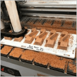
The strum hollow and tail portions of the dulcimer fretboard require 3 Axis machining operations. They take advantage of the roughing capability incorporated into RhinoCAM’s 3 Axis Parallel Finishing toolpath strategy. They also illustrate some Best Practices for 3 Axis machining such as using masking surfaces to guide the toolpaths over and around critical areas and the use of overlapping closed 2D planer containment regions. On the left below we see the completed fretboard shown on the CNC machine. On the right we see the completed dulcimer with the fretboard strum hollow and tail shown.
 |
 |
 The machining job tree shown here includes the toolpath operations for the fretboard tail. Two 3 Axis Parallel Finishing operations are used for roughing and two are used for finishing. The strum hollow uses separate but identical operations. All dimensions mentioned are in Inches.
The Part & Stock Models
In the left side image below we see the 3D surface model of the fretboard in Rhino. On the right we see the stock model (30” x 1.750” x 0.8”) shown translucent over the part model. The surfaces shown in red serve the purpose of protectively masking critical edges that Terry wants to keep the tool away from. In 3 Axis machining RhinoCAM incorporates automatic gouge-free machining of all visible surface geometry. You can also see 2D closed planar curves (shown in blue) that serve to contain the toolpaths in X and Y. The underlying surfaces will automatically contain the toolpaths in Z.
 |
 |
Parallel Finishing in Levels (for Roughing)
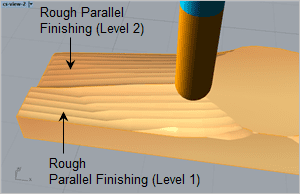
To rough out the fretboard stock, Terry uses four 3 Axis Parallel Finishing operations, two for the strum hollow (right & left) and two for the tail (right & left). The stock allowance parameter and the Step-down Z Cuts option on the Z Containment tab of the Parallel Finishing operation are used for roughing. For this job Terry is using 2 cut levels. You can refer to the image descriptions below for more cutting details.
- (A) We see a closeup of the fretboard tail as well as the 2D planar closed curve containment regions that are split right and left. The regions overlap 0.10” along the center line and are used to contain each 3 Axis toolpath. We also see a closeup of the masking surfaces (shown in Red). The surface that extends past the end of the tail will keep the tool from rolling over the edge, producing a nice even edge. The other masking surfaces perform a similar function. Also shown as reference is the Nut & Bridge model.
- (B) Here we see both Rough Parallel Finishing operations (right & left) using a ½” diameter ball mill at a stepover of 25% and a mixed cut direction. When both operations are selected from the Machining Job tree both are displayed together on the part.
- (C) The 3 Axis Parallel Finishing operation supports multiple Z stepdown levels making the operation ideal for roughing tasks. In this image we see the Z Level Display dialog with the first of two cut levels selected. The remaining stock allowance is set to 0.1”.
- (D) Here we see the second rough cut level of the 3 Axis Parallel Finishing operations. Notice how the masking surface (shown in red) forces the cutting tool past the edge of the fretboard tail!
 The fretboard tail, stock, containment regions and masking surfaces are shown. |
 Both Parallel Finishing toolpaths (right & left) are shown. |
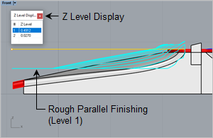 The first Parallel Finishing cut level is displayed. The yellow line indicates the z location of the containment regions. |
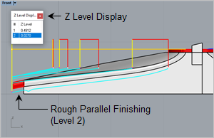 The second Parallel Finishing cut level is shown with a clean extension onto the masking surface (red). |
Parallel Finishing (for Finishing)
To finish the fretboard stock, Terry again uses four overlapping 3 Axis Parallel Finishing operations, two for the strum hollow (right & left) and two for the tail (right & left). These operations differ from the previous roughing operations with the stock allowance set to zero and Step-down Z Cuts disabled from the Z Containment tab.
- (A) On the left we see the cut material simulation for the previous Parallel Finishing operations with the remaining stock allowance set to 0.1”. It shows the right-side operation at cut level 1 and the left side operation at cut level 2. The two right and left cuts overlap by 0.10” along the centerline.
- (B) On the right we see the final finishing cut material simulation for the Parallel Finishing operation with the remaining stock allowance set to zero but with Step-down Z Cuts disabled. The stepover is set to 5% (0.025”).
 The cut material simulation for the Parallel Finishing operation with two Z levels defined. |
 The cut material simulation for the final Parallel Finishing (right side toolpath is shown). |
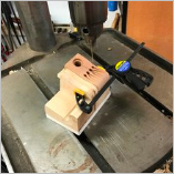
More Studio Pics
Here are some additional images from Terry’s studio. For more information about Terry McCafferty and the quality Appalachian dulcimer instruments that he crafts we invite you to visit him online at mccaffertydulcimers.com and on Facebook at facebook.com/mccaffertydulcimers/. Enjoy the craftsmanship!
 |
 |
 |
 |
 |
 |
 |
 |
| Cool studio picks from McCafferty Dulcimers | |||


