CONTENTS:
Editor’s Notes:
- This tutorial is shown in VisualCAD/CAM. The Profile-NEST module functions identically in versions of RhinoCAM, VisualCAM for SOLIDWORKS and AlibreCAM.
- Click here to download the source files used in this tutorial.
- This article is a higher level guide to using Profile-NEST. For a more step-by-step approach it is recommended that you visit the More Resources section at the end of this article for links to the Profile-NEST Quick Start Guides.
About Profile-NEST
 Profile-NEST is an add-on module that is included in each of MecSoft’s desktop CAM products VisualCAD/CAM, RhinoCAM, VisualCAM for SOLIDWORKS and AlibreCAM. Profile-NEST can also be run as a stand alone system with MecSoft’s free CAD drawing program VisualCAD. Profile-NEST is available free to all MecSoft desktop CAM Standard configurations product users who are active on their annual maintenance subscription. Profile-NEST appears as an added module on your MecSoft CAM main menu.
Features
Profile-NEST is a fully functional CAM system for programming 2½ Axis Profiling toolpaths and nesting those toolpaths onto one or more sheets of stock material. The Profiling toolpath strategy includes all of the cutting parameters found in MecSoft’s flagship desktop product such as automatic bridges & tabs, cut arc fitting, advanced cornering options and more. Nesting features include custom sheet size and thickness, part priority, orientation and grain direction control, overflow utilization, auto-tag options and more.
Plasma & Laser Cutter Applications
Profile-NEST is targeted toward CNC controlled Plasma and Laser cutting applications. Plasma is a process that cuts through electrically conductive materials by means of an accelerated jet of hot plasma. Materials cut with a plasma torch include steel, stainless steel, aluminum, brass and copper. Laser cutting is a technology that uses a laser to slice non conductive materials such as wood, cork, paper and foam among others, except for most plastics which will melt under the heat of the laser.nLasers are also used in etching on glass, tile, aluminum or stone. Plasma is used primarily in industrial cutting applications. Laser cutting is safe enough to be used by schools, small businesses, and hobbyists.
Profile-NEST Workflow
A typical workflow for utilizing the Profile-NEST module within the context of the MecSoft CAM system is a simple 4-step process:
1. Step 1: Stage your Parts: This initial step involves gathering and positioning the part geometry whose profiles that you plan to nest. The geometry can be simple 2D curve profiles or complete 3D surface or solid bodies.

2. Step 2: Setup your Machining Job: This step begins your machining strategy by setting up your Post-processor, Sheet size and Stock material.

3. Step 3: Toolpath Your Profiles: In this step you will create your 2½ Axis Profiling toolpath operations on each of your part profiles. This step includes all cutting parameters, part specific nesting parameters, cutting tool definition, feeds & speeds, cornering parameters and more.
4. Step 4: Execute your Nest & Post: This final step includes all nest specific parameters such as distance and orientation between profiles, tagging and sorting options, # of sheets, nesting previews, reports, simulations and g-code post-processing.

Step 1: Stage your Parts
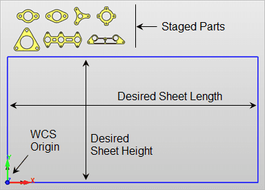
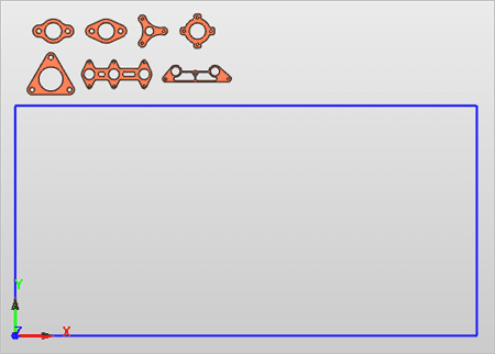
In Profile-NEST there is only one instance of each part you want to nest. In our example we have a total of 7 parts that we want in our nest. These parts can be defined by 2D curves or 3D surfaces or solid models. Our parts are 3D solids. It is important to note the positioning of your parts in this step. Since you will be viewing your parts and nested sheets together you need to locate your parts outside of your desired sheet size on the XY plane. The bottom of your parts should be located at Z 0.0 (zero). There is no need to draw the sheet rectangle. We show it in the image below for illustration purposes.

Step 2: Setup your Machining Job
When you first load the Profile-NEST module the Machining Browser will look like this. It consists of several tabbed menus at the top, a Machining Job tree and a toolbar for display toggles at the bottom. Starting from left to right, the first tab toggles through the available modules, the second smaller tab toggles the display of the Machining Objects Browser (bottom portion of the browser) and then is followed by the Nest tab and the Simulate tab.

Here is what the display will look like when the nesting is complete. The completed version of this part is included in the source files download link at the top of this page.

Post Selection
For the Post definition we have it set to Mach3-Plasma. You can choose from over 300 pre-configured post-processors and use the included post-processor generator to customize your post. The Post menu option and updated Machining Job are shown below.

Sheet Definition
Next you will setup your nested sheet size. In our example we have a sheet that is 96 x 48 x 0.25 in size. The Sheet Definition fields of the Select Sheets dialog are used to do this. If you have a rectangle drawn for the sheet, make sure it’s bottom left corner is located at WCS 0,0,0.
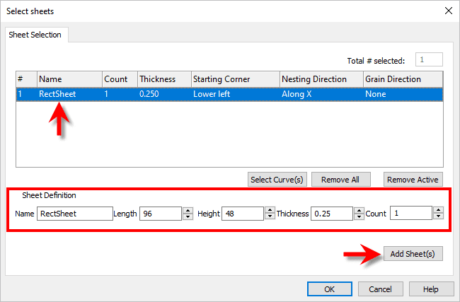
When you pick OK from the Select Sheets dialog your display will look like this:
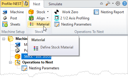
Stock & Material
Now that the sheet is defined, let’s define the stock. We’ll be using a Box Stock. The menu selection and dialog with parameters are shown below. In the Box Stock dialog enter the stock size and make sure the Corner Coordinates are set to 0,0,0 and the the bottom left corner is selected from the dialog as shown.


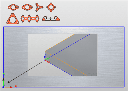
After you pick OK from the Box Stock dialog your stock will display on the screen. If it doesn’t toggle the stock on using the button provided in the Machining Browser. See Step 2: Setup your Machining Job above for the location of these display toggles.
For Material you can use the Select Stock Material dialog to select one of the materials in the list. However, the material definition only comes into play if you use the Load from File option to set your feeds and speeds for either the tool or the operation. The Load from File option displays a dialog that is similar to a feeds and speeds calculator. Here is what we have selected for Material.

After you pick OK from the Material dialog, the material texture will display on the stock. If it does not, select the Material Texture display toggle button from the Machining Browser. Again, see Step 2: Setup your Machining Job above for the location of these display toggles.
Step 3: Toolpath your Profiles
In this step you will create the 2½ Axis Profile toolpath operation for each part. In Profile-NEST each profile toolpath is nested, so we want one 2½ Axis Profile operation for each part. Here are the parts we want to nest. We have numbered them in this illustration for simplicity.

Here is the menu selection for 2½ Axis Profiling.

The 2½ Axis Profiling operation dialog will display. All parameters in each tab have default values so we will not be looking at each tab in the dialog in this tutorial. We’ll be covering the tabs and parameters that you need to look at. For a quick start using 2½ Axis Profiling refer to the More Resources section at the bottom of this article and locate the MILL Quick Start Guide.

Control Geometry
From the Control Geometry tab we will pick the Select Flat Area Regions button. The dialog will minimize. Then we will select the flat surface at the top of Part #1 and then accept the selection. The dialog reappears and lists Drive Flat Area 1 in the Part Regions section of the dialog as shown below.

Tool Selection
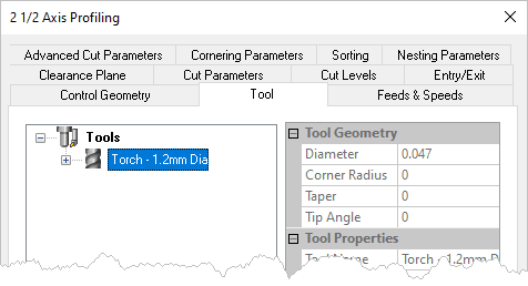
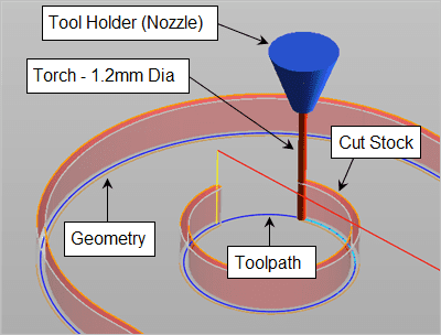
From the Tool tab of the dialog we will select the Edit/Create/Select Tool button. This will display the Create/Select Tool dialog so that you can define a tool. For plasma cutting you only need to be concerned with the torch diameter. We have created a flat end mill tool with the specified diameter 0.047 of the plasma torch. We have set our CAM Preferences for Cutting Tool to the colors you see for the tool preview in the dialog.

For the Cut feed we select the Feeds & Speeds tab of the dialog and set the value to 120 in/min and then pick OK.

Our Torch – 1.2mm Dia tool is now listed in the Tool tab of the 2½ Axis Profiling dialog.
Cut Parameters
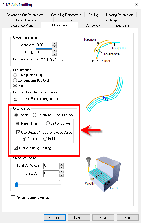
We switch to the Cut Parameters tab and set the Cutting Side section of the dialog to the following selection. Our parts have interior cutouts so these selections will ensure the cut side is correct for both the outer perimeter and the inner cutouts.
Cut Levels
Our sheet is 0.250 so on the Cut Levels tab we select At Top for the location of cut geometry (i.e., we selected the top face of the part) and then set the Total Cut Depth to 0.25. This automatically sets the Rough Depth and Rough Depth/Cut to 0.25 also. This is what we want.

Part Nesting Parameters
Now we switch to the Nesting Parameters tab and set the Count to 40. This is the total number of this part we want included in the nest.

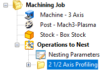
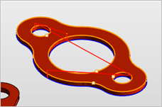
Now we pick Generate from the dialog to create our first 2½ Axis Profiling toolpath. The operation is listed under Operations to Nest in the Machining Job and it is also displayed on the part. If you do not see the toolpath, there is a display toggle for this also.
 |
 |
Copy/Paste Toolpaths
Now that we have Part #1 programmed we can easily program the remaining parts by using Copy/Paste/Edit on our first toolpath. We right-lick on the operation in the Machining Job and select Copy. We right-click again and select Paste. This creates a copy of the toolpath under the original. We do this 5 additional times until we have the original and 6 copies as shown below.

Now we will rename the first toolpath. Right-click on it and select Rename from the menu (or just double-left-click on the name to edit it.) and change the name to 2½ Axis Profiling (Part #1) and press enter. Do this for the remaining 6 toolpaths until the Machining Job looks like this:

Now we need to assign Part #2 through Part #7 to its respective toolpath operation. Select 2½ Axis Profiling (Part #2) from the Machining Job, right-click and select Edit to display it’s operation dialog. From the Control Geometry tab pick the Remove All button to remove the flat area from the list. Then pick the Select Flat Area Regions button and this time select the top face of Part #2 and then accept the selection.

We do this for each remaining part. When done each 2½ Axis Profiling operation in the Machining Job will have its associated part number assigned to it.
Step 4: Execute the Nest
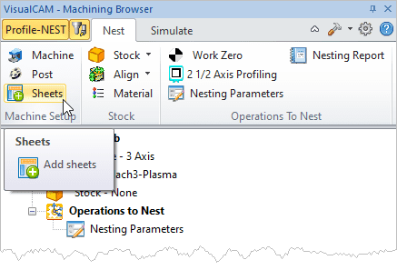
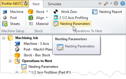
Now, with a 2½ Axis Profiling operation programmed for each of our parts we can turn our attention to nesting them onto sheets. For this we select Nesting Parameters from the Nest tab of the Machining Browser and use the Nest Params dialog.
Nesting Parameters
You can set the parameters on this dialog to your specific job requirements. We have the Orientation Step Angle set to 45 allowing each part to rotate in 45 degree increments. If you recall we have our torch cutting tool diameter set to 0.047 and we now have our Distance Part to Part and Distance Part to Sheet set to 0.1. These distances are measured from the toolpath (i.e., the center of the tool) and not the edges of the parts. You can increase these distances to suit your specific cutting results.

We also have the Nested Sheet Layout set to Stack. This places each nested sheet on top of each other so that all toolpaths are measured from the WSC origin of 0,0,0.
With our nesting parameters set we select the Estimate # of Sheets button to see how many sheets will be required to nest a total of 40 pieces for each of our 7 parts.

The dialog tells us that 3 sheets will be required so we select the Update Sheet Count button to set our sheet count to 3 and then pick OK to close the dialog.
Execute & Preview the Nest
Now we’re ready to nest our 2½ Axis Profiling operations onto sheets. With the Nesting Parameters dialog still displayed we select the Execute Nest button. The nest is calculated and each sheet is added to the Machining Job.

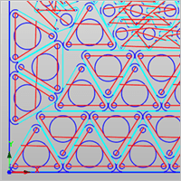
Selecting a Sheet from the Machining Job will display the nested 2½ Axis Profiling operations for that sheet. Remember to have the display of Toolpath toggled on from the Machining Browser. Again, see Step 2: Setup your Machining Job above for the location of these display toggles. Here is what each nested sheet looks like:
Nested Sheet #1:

Nested Sheet #2:

Nested Sheet #3:

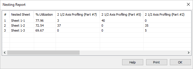
You can also get a nesting report. This command is located on the Nest tab and displays a report of the sheets and parts on each sheet.

Simulate & Post
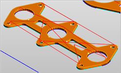
You can perform a cut material simulation on your part profiles or on one or all of the nested sheet profiles. Before simulating your part profiles, make sure to adjust your stock width (i.e., Y axis height) to reach your parts that are located outside of your sheet. In this case we set the stock dimensions to L: 96, W: 72 and H: 0.25.
Then we change to the Simulate tab, select 2½ Axis Profiling (Part #2) from our Machining Job and then pick Play. You can adjust the simulation colors from the Simulation tab of the CAM Preferences dialog.
To post-process a sheet, just select it, right-click and select Post from the menu. From the Post & Save As dialog, select a folder to locate the g-code file and pick Post.


Part & Nest Revisions
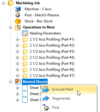
You can make any adjustments to the Machining Job including any operation under your Operations to Nest or your Nesting Parameters. Your Nested Sheets will then become flagged. Just right-click on Nested Sheets and select Execute Nest to update your nested sheets.
Let’s Review
Let’s take a moment to review what we have learned in this tutorial:
- How to get Profile-NEST: We learned that the Profile-NEST module is part of MecSoft’s desktop CAM plug-ins including VisualCAD/CAM, RhinoCAM, VisualCAM for SOLIDWORKS and AlibreCAM. We learned that as long as your Annual Maintenance Subscription (AMS) is active, this module is yours to use free of charge beginning with the MILL Standard configuration.
- Stage your Parts: We learned that executing a Profile-NEST is a 4-step process and that locating your parts outside of your nested sheet area will allow you to view them together on the screen.
- Setup your Machining Job: In this step we learned how to define your Post-processor, how to define your nested sheet size as well as the stock size, position and material.
- Toolpath your Profiles: In this step we learned how to create a 2½ Axis Profiling operation for each of our parts including the cutting torch (Tool) definition, cutting parameters, cut levels and nesting parameters.
- Execute the Nest: In this final step we learned how to execute, preview, get a nesting report and perform a cut material simulation. We also learned how to make revisions, update and execute our nested sheets and how to post process a sheet to output g-code.
More Resources
Want to learn more about the Profile-NEST module in MecSoft’s desktop CAM plug-ins? Check out some of these resources:
VisualCAD/CAM |
RhinoCAM |


