PART 1 CONTENTS:
Editor’s Note:
This tutorial is shown in RhinoCAM. The G-Code Editor module functions identically in VisualCAD/CAM, VisualCAM for SOLIDWORKS and AlibreCAM.
- To download the source files used discussed in this tutorial, click here.
- This tutorial is published in 2 parts. Click here to read Part 2.
About G-Code Editor
 G-Code Editor is a software module included with MecSoft’s desktop CAM plug-ins including VisualCAD/CAM, RhinoCAM, VisualCAM for SOLIDWORKS and AlibreCAM. The G-Code Editor module is available free of charge to all McSoft users who are active on their Annual Maintenance Subscription (AMS)! Plus, there is no added software to download and install. As long as your AMS subscription has not expired the G-Code Editor will appear as an added module on your CAM Main Menu!

What is G-Code?
Simply put, G-Code is a machine language that instructs Computerized Numerical Control (CNC) systems how to get from point A to point B in 3-dimensional space (i.e., in X,Y,Z). It is named after the type of geometry (G) and machine (M) codes the language employs such as G0/G1: straight lines, G2/G3: arcs, M5 machine spindle stop, etc. CNC machines are used in subtractive manufacturing for removing material from a stock using a variety of cutting tools and methods such as hardened steel and carbide mills, plasmas, lasers, and even water jets.
What is a G-Code editor?
While there is an international standard (ISO 6983) for how G-Code files are formatted, there are many different types of CNC machines, each one expecting the G-Code program to be written in a slightly different way. This facilitates the need for an editor that can open G-Code files and allow the operator to make changes to the code before the program is sent to the CNC machine. While similar to a standard text editor, the G-Code Editor module does have additional tools and utilities specifically designed for viewing and editing G-Code files that are produced by one of MecSoft’s CAM plug-ins. These include a visual representation of the G-Code, referred to a backplot, G-Code text search, tool motion analysis, cut material simulation, etc.
A Typical Workflow
A typical workflow for utilizing the G-Code Editor module within the context of the MecSoft CAM system is a simple 3-step process:
1. Generate: Use the MecSoft CAM MILL module to create your toolpath strategies. While in the MILL module, your toolpaths are stored internally and saved with your native CAD file. While in the CAD system your toolpaths are not yet G-Code files.
2. Post-Process: Once you are satisfied with the CAM operations, you post-process them to one or more G-Code files using one of over 300 post-processors that are included with MecSoft CAM. The post-processor you choose will be tailored specifically for your CNC machine’s controller software. If you wish to perform tool motions and cut material simulations within the G-Code Editor, it is best to also save your cutting tools to a tool library file if you have not already done so.
3. Edit & Save: You then launch the G-Code Editor module, load the G-Code files you created in step 2, perform manual edits to the code as desired and then save them back out. Once in the G-Code Editor, you only need to work with the G-Code files to load, make edits and save. You can also load your tool library to analyse the G-Code file with the actual tools you plan to use on your CNC machine.
Loading & Saving G-Code Files
Once we have completed Steps 1 & 2 (see A Typical Workflow above) we have several G-Code files that we have posted from our Machining Job. We are now ready to start using the G-Code Editor. Here are the basic steps to launch the G-Code Editor module and load a G-Code file for editing. We will be using the RhinoCAM plugin operating within Rhino 6.0 for this demonstration. The procedures will be the same for each desktop platform.
1. In our example part we have programmed several 2½ Axis and Hole Making toolpaths using the MILL module in RhinoCAM. Below is how the part and Machining Job tree looks in RhinoCAM-MILL. Here is a closeup of the Machining Job tree:
2. From the RhinoCAM Main Menu we select G-CODE EDITOR and the G-Code Editor Browser displays on the left side of the screen by default. As in all MecSoft CAM modules you can dock or undock the browser to any location on the screen that you wish.

3. From the Project tab of the G-Code Editor Browser we select Load.

4. We navigate to the folder where our G-Code files are located, select a file and pick Open.
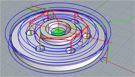
5. The name of the G-Code file is listed in the Project tree along with a list of the cutting tools that the file references. The G-Code is immediately back plotted and displayed on the screen along with the part.

6. Our G-Code file “Part1_Setup1.nc” was created by posting the entire Setup1 from RhinoCAM-MILL and includes ALL 7 of our toolpath operations. Here is what our Project Tree looks like after loading the G-Code file: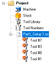
7. Since our G-Code file references 4 different cutting tools (#1, #3, #7 and #8), each one is listed under the file within the Project tree. There are red flags displayed to the left of each tool to let you know that these tools have not yet been defined within G-Code Editor. Refer to Defining the Tool Crib below.
8. You will notice that the back plot of the G-Code file is color coded.
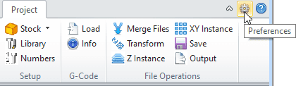
9. You can change these colors from the G-Code Editor Preferences dialog. Select this icon ![]() to display the Preferences dialog and navigate to the Toolpath section as shown below:
to display the Preferences dialog and navigate to the Toolpath section as shown below:

10. From here you can also control the display thickness of the back plot and set other toolpath related preferences.
11. To perform some quick edits to the G-Code just double left-click on the file name in the Project tree or right-click and select Edit from the menu.
12. Pick Yes from the message dialog to use a default tool and the G-Code contained in the file is loaded into the Edit tab of the Browser. 13. From here you can make edits to the G-Code and then select Save to save the changes.

How Cutting Tools are UsedWe described above how you can use G-Code Editor to load, edit and save your g-code files. You can use these tasks to make reviews and quick edits to your g-code before sending it to your CNC machine. We also mentioned that G-Code Editor understands when tool changes are made in your g-code. In this section we will explore how G-Code Editor takes advantage of this tool information.
Tool Changes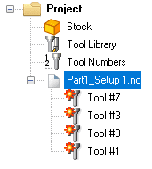 When you load a file into G-Code Editor it scans the g-code and makes note of the tool numbers that are used and lists those tools under the g-code file name in the Project tree as shown here. G-Code Editor supports Tool Libraries and Tool Cribs. The Tool Library contains a collection of tools representing those that are available in your shop. This is the same tool library that is also supported by the MILL module.
The Tool Crib represents a collection of tools that are available to this specific g-code program, similar to a set of tools that are loaded into an automatic tool changer on the CNC machine at the time the g-code program is run. In the Project tree here you see that all four of the tools referenced in our g-code file are flagged. This simply means that these tools were not found in the current tool crib. The topics below show you how to load a Tool Library and define the Tool Crib.
Loading the Tool LibraryThe Tool Library in G-Code Editor is a file (example: my-tool-library.csv) that you create from the MecSoft CAM MILL module. After defining your set of tools and you see them listed under the Tools tab of the Machining Objects Browser perform the following procedure:
1. Launch your MecSoft CAM product and load the MILL module.
2. From the Tools tab of the Machining Objects Browser you should see your tools listed as shown below: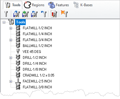
3. From the Tools toolbar select the Save Tool Library ![]() icon.
icon.
4. The File Save As dialog displays asking you to provide a name for the file. MAKE SURE the Save as type field is set to Tool Library Files (*.csv). Then enter a name and pick Save. You should receive a message saying that # tools were saved to the tool library file.
5. Now load the G-Code Editor module and from the Project tab select Load from the Library menu as shown below.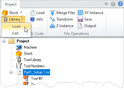
6. From the File Open dialog navigate to and select the Tool Library file you just created and then pick Open. G-Code-Editor opens the Tool Library and displays the list of tools it contains. You can filter the tool list by tool type using the toolbar at the top of the dialog.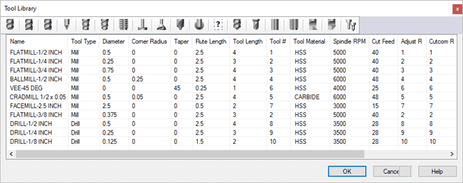
7. Now pick OK to close the Tool Library.
Defining the Tool CribThe Tool Crib is a subset of the active Tool Library. It should contain the tool numbers requested by the g-code file. We will follow these steps to define the Tool Crib.
1. In G-Code Editor with the g-code file loaded, select Numbers from the Project tab.


