 MecSoft is proud to announce the new Post-Processor Decoded Guide. Many of you have specifically asked that we write a comprehensive and easy to follow guide on how the PPG (Post-Processor Generator) operates. This guide is included in the CAMJam Self Training archive, available to all MecSoft users who are active on their Annual Maintenance Subscription (AMS). Click here to learn how to download CAMJam.
What’s Inside
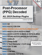
This guide teaches you about the Post-Processor Generator (PPG) and post-processor definition files and how they are used to format and control the out output of your G-Code files. We start with a basic example part that utilizes 12 of the 15 PPG sections, including Tool Changes, Circle/Helical Interpolation, Cutter Compensation and Canned Cycles. We then post a sample G-Code file and color-code every line with the PPG section that controls it! You will also learn about the macros and variables used by each section of the PPG for the sample G-Code and post.

You will learn about Cutter Compensation, the correct steps needed to implement it bot in MecSoft CAM and in your CNC controller.
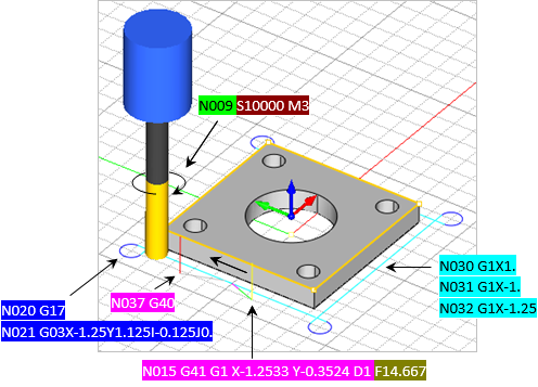

You will learn how to post Arc motions in your G-Code for increased accuracy, smaller G-Code files, increased performance and less wear and tear on your CNC machine. This guide also teaches you about the I,J,K Arc format, how it is calculated and how to read it on your G-Code files.

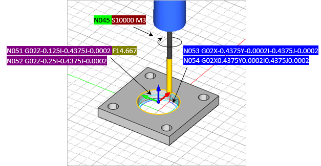
You will also learn about helical motions and how they differ from Arc in the posted G-Code. How to make sure Arcs and Helical motions are being posted in your G-Code (G02 and G03) and also where to go in MecSoft CAM to control their format.

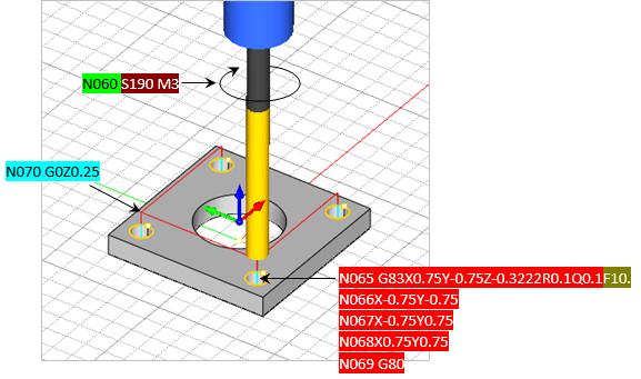
The guide does not stop there! You will even learn about canned cycles and specifically how to implement the G83 Deep Drill cycle and each of the variables that are assigned to the various Cut Parameters you see in the Drilling operation dialog.
Want More?
How about learning about every PPG variable that was used to post the G-Code for these three sample toolpath operations and where the variable value was derived from!
Here is the complete Table of Contents:
What is a Post-Processor?
What is the Post-Processor Generator (PPG)?
PPG Variables & Macros
Decoding a Sample G-Code File
The Setup & Post Processor
The Sample Toolpaths
The Posted Setup G-Code File
The 2½ Axis Profiling Operation G-Code
The 2½ Axis Hole Profiling Operation G-Code
The Deep Drilling Operation G-Code
The Post-Processor Generator Dialog
PPG > General
PPG > Start/End
PPG > Tool Change
PPG > Setup
PPG > Spindle
PPG > Feed Rate
PPG > Motion
PPG > Circle
PPG > Helical/Spiral
PPG > Multi Axis Motion
PPG > Cutter Compensation
PPG > Cut Motion Start/End
PPG > Cycles
PPG > Misc
PPG > Variables
Download the Resource files
As an annual MecSoft AMS subscriber you can download the source files for this guide as part of your CAMJam 2019 training archive package. It includes the sample part file with geometry and three machining MOps pre-defined in VisualCAD/CAM, RhinoCAM, VisualCAM for SOLIDWORKS and AlibreCAM.
Here is the complete source file list includes:
- The part file and Toolpaths in *.vcp format (VisualCAD/CAM)
- The part file and Toolpaths in *.3dm format (RhinoCAM for Rhino 6)
- The part file and Toolpaths in *.sld_prt format (VisualCAM for SOLIDWORKS)
- The part file and Toolpaths in *.AD_PRT format ( AlibreCAM)
- The Tool Library and Knowledge Base Files in vkb format.
- The sample haas-blog.spm post definition file.
- The sample G-Code file illustrated in this guide.
More about MecSoft CAM Products
For more information about each of these Mill Module products, including data sheets, videos and other resources we invite you to visit the following product pages:


