The “Maze” RhinoCAM at Universitat Internacional de Catalunya School of Architecture

Search

Blog Categories

This cool case study comes to us courtesy of Affonso Orciuoli, Associate Professor and Research Assistant for the Architecture Graphics Department at the Institute for Biodigital Architecture & Genetics, Universitat Internacional de Catalunya School of Architecture in Barcelona Spain. Affonso is also a Rhino and RhinoCAM reseller! We sat down with Affonso to get a first-hand look at The MAZE project.

The RhinoCAM Difference!

Because RhinoCAM works inside of Rhino. We do not need to export, import… That means if we change the project design, we can update the toolpaths in one click! Another important issue is that RhinoCAM is so intuitive. That helps a lot for students that are not familiar with CAM technology. And finally, support and feedback! Every time I need some help, the MecSoft support answers my questions very quickly!

prof. arq. Affonso Orciuoli – Distribuidor Autorizado McNeel Brasil
McNeel & Associates, Kirkland, Washington

The “MAZE” Project

“During the master “BioDigital Architecture”, we dedicate 2 weeks to introduce students to Digital Fabrication. We have a laser cutter, an AXYZ router (3 axis) and 2 Felixprinters (FDM 3d printer). So, we provide 1 block of FOAM, with 50 mm depth. They can create an abstract project inside the block. So, using RhinoCAM, they need to program the machine. Also, we manage the time, and we allow them to use just 4 mills. Students can combine other material and techniques to their work.” 
Here is a very cool video produced by the staff and students involved in this project:
“THE MAZE” Prof. arq. Affonso Orciuoli, Associate Professor | Research Assistant Architecture’s Gr…

The CAD Geometry

The illustration below shows how the geometry looks when it is rendered in Rhino. The geometry consists of a series of leveled terraces that are interconnected. There are a total of 20 levels each consisting of a stair that is 4mm wide and 2 mm deep.
In this illustration, you can see the rendered image from Rhino 7 of “THE MAZE” geometry

The Stock & Setup

Add Your Heading Text Here

The stock material for this project is medium density foam measuring 1480 x 510 x 40 millimeters (approx 60 x 13 x 1 inches and is defined as a Part Box Stock in RhinoCAM. This means that the stock dimensions are extracted from the bounding box dimensions of the part geometry. The Post-processor is set to Mach3-MM. The Machine is set to 3 Axis, no Fixtures are defined and there is one setup called Setup 1. This information is defined by the first 4 objects listed in the Machining Job as shown here.

Sequence of Operations

Under Setup 1 in the Machining Job there are seven items listed for machining. The first operation is a 3 Axis Horizontal Roughing toolpath using a 20mm diameter flat end mill. This will remove much of the bulk material and prepare the stock for finishing. This is followed by a 3 Axis Parallel Finishing and 3 Axis Horizontal Finishing operation both using a 4mm diameter ball mill cutter. The Parallel Finishing operation is shown for reference to illustrate the different results between the two finishing operations. Horizontal Finishing works best on prismatic parts with vertical walls, like this project. Whereas the Parallel Finishing method works best when the part has contoured geometry that needs to be cut.

The next item in the Machining Job is a MOp Set. This is short for a Machining Operation Set. Operations can be grouped when they are similar or when they use the same cutting tool. The operations in the MOp Set are three 2½ Axis Pocketing operations each using a 4mm diameter flat end mill cutter. These pockets are locating channels for the three 3D Printed attachments shown in the final images below.

3 Axis Horizontal Roughing (20 Dia FM)

The first toolpath under Setup 1 in the Machining Job is a 3 Axis Horizontal Finishing operation. It uses a 20mm diameter flat end mill cutter. The Spindle Speed is set to 12,000 RPM and a cut fee rate of 2000 mm/minute. The operation’s Control Geometry is set to the outer perimeter rectangle of the part and an in/out tolerance of 0.25mm and stock allowance of 1mm. An offset facing cut pattern is used with a conventional (up cut) cutting direction. The stepover is set to 80% of the tool diameter (16mm). The stepdown control is set to a distance of 5mm with Depth First Level Ordering. This means that each tarrice is cut to its depth before moving to the next. Entry and Exit is set to Ramp and Arc Fitting is applied. The images below show the toolpath on the left as well as the cut material simulation on the right.
Toolpaths for the 3 Axis Horizontal Roughing Operation
The cut material simulation for the 3 Axis Horizontal Roughing Operation

Add Your Heading Text Here

Lorem ipsum dolor sit amet, consectetur adipiscing elit. Ut elit tellus, luctus nec ullamcorper mattis, pulvinar dapibus leo.

The first toolpath in the Machining Job is a 3 Axis Horizontal Roughing operation using a 20mm diameter flat end mill cutter. A portion of the toolpath is shown on the left and the resulting cut material simulation is shown on the right.

3 Axis Parallel Finishing (4 Dia FM)

The next operation in the Setup is 3 Axis Parallel Finishing using a 4mm diameter flat end mill cutter. Again the Spindle Speed is set to 12,000 RPM and a cut fee rate of 2500 mm/minute. The cut tolerance is set to 0.03mm and stock allowance of 0mm. For Cut Control the cut direction is set to Mixed, the start side is set to Bottom, the angle of cut is set to 0 (i.e., along the X axis) and the stepover is set to 75% of the tool diameter (3mm). Entry and Exit is set to Linear with an approach distance of 0.6. Cut connections are straight. The images below show the toolpath on the left as well as the cut material simulation on the right. On the left image, make note of the “cusping” material remnants left on the vertical side walls of the stock. This occurs because the cutter paths are parallel and limited to moving only along the X axis. This is the inherent constraint of 3 Axis Parallel Finishing.


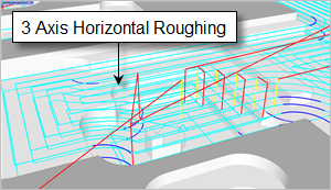
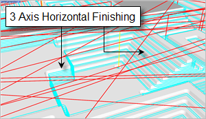
What is Scalloping and How to Avoid it?

A Scallop is material that is left after a machining operation. It is a result of the stepover distance being too large in relation to the cutter diameter. Scalloping can occur w hen a ball mill cuts geometry that is not vertical or when an end mill cuts geometry that is vertical. To minimize scalloping use a smaller stepover. In this case we can eliminate it by using 3 Axis Horizontal Finishing operation.

Toolpaths for the 3 Axis Parallel Finishing Operation
The cut material simulation for the 3 Axis Parallel Finishing Operation
Here we see a 3 Axis Parallel Finishing operation using a 4mm diameter flat end mill. This operation type is not suitable for vertical walls. In the cut material simulation on the right, you see the “scalloping” effects left on vertical walls that do not lie parallel to the cut direction and would require further finishing. Scalloping can be avoided by using 3 Axis Horizontal Finishing.

3 Axis Horizontal Finishing (4 Dia FM)

To clean up the scallops left after the previous operation, the next operation in the Setup is 3 Axis Horizontal Finishing using a 4mm diameter flat end mill cutter. Again the Spindle Speed is set to 12,000 RPM and a cut fee rate of 2500 mm/minute. The cut tolerance is set to 0.03mm and stock allowance of 0mm.

For Cut Control the cut direction is set to Climb, the Stepdown (dZ) is set to 2mm and Cut Levels Ordering is set to Depth First. This means that every pocket is cut to depth before moving on to the next. Entry and Exit is set to None so the tool will plunge from the clearance plane to engage and then retract to the clearance plane to end the cut motion.
A Time-Saving Combination!For parts that are prismatic (i.e., mostly vertical walls and flat pockets and plateaus, using Horizontal Roughing with Horizontal Finishing is the best combination. Why? Because you can enable the Clear Flats” option in Horizontal Roughing that will finish all flat areas, only leaving the stock allowance on the vertical walls. Then using Horizontal Finishing will finish all vertical walls! This is a true winning combination for finishing prismatic parts like these!
Toolpaths for the 3 Axis Horizontal Roughing Operation
The cut material simulation for the 3 Axis Horizontal Roughing Operation
Here we see a 3 Axis Horizontal Finishing operation using a 4mm diameter flat end mill. This operation type is very suitable for vertical walls. In the cut material simulation on the right you see that no scalloping occurs.

2 1/2 Axis Pocketing (4 Dia FM)

The next operation in the Machining Job tree is a MOpSet. This is a “container” folder that contains three 2½ Axis Pocketing operations cut again using the 4mm diameter flat end mill. Each pocket is 2mm deep cut in one cut level using an Offset Cut Pattern with a Ramp entry motion and a linear retract motion. These pockets will be the location of three 3D Printed components that will be fixed in place using adhesive. These added components give the final work the allusion of an organic structure that is literally growing up and out of the MAZE complex. This is a very interesting design concept!
Toolpaths for the 2½ Axis Pocketing Operation
The cut material simulation for the 2½ Axis Pocketing Operation
Here we see the 2½ Axis Pocketing operation using a 4mm diameter flat end mill and an Offset Cut Pattern.
Here we see one of the 3D printed components being mounted in the 2½ Axis Pocket. These components were manufactured using the school’s 3D Felixprinters FDM (Fused Deposition Modeling) 3dprinter.
Cool Teacher/Student project Pete!
Thank you for allowing us to showcase your work!

More About Affonso Orciuoli

Architect by FAU Mackenzie (São Paulo), Master of the Escola Tecnica Superior d’Arquitectura (Universitat Politècnica de Catalunya). He is a teacher, blogger, lecturer, entrepreneur and researcher on new technologies applied to digital design and manufacturing. Professor at the School of Architecture, Universitat Internacional de Catalunya (UIC) and at the Istituto Europeo di Design – Barcelona. He dedicates himself to the digital fabrication, the programming of G-code for milling machines and 3d printers, computational geometry and to teach a new craft, which he calls “digital craftsmanship.”

More about RhinoCAM

RhinoCAM – MILL from MecSoft Corporation is available in five different configurations (Express, Standard, Expert, Professional and Premium). The part shown here was programmed using the Standard configuration. Here are some additional details about each of the available configurations. For the complete features list, visit the RhinoCAM Product Page.

  • RhinoCAM MILL Express: This is a general-purpose program tailored for hobbyists, makers and students. Ideal for getting started with CAM programming. Includes 2 & 3 axis machining methods. Includes ART & NEST modules as well!
  • RhinoCAM MILL Standard: This configuration includes everything that is in the Express configuration and additional 2-1/2 Axis, 3 Axis & Drilling machining methods. Also now includes 2½ Axis Turning!
  • RhinoCAM MILL Expert: Suitable for 4 Axis rotary machining. Includes the Standard configuration, plus 4 Axis machining strategies, advanced cut material simulation and tool holder collision detection.
  • RhinoCAM MILL Professional: Ideal for complex 3D machining. Includes the Standard and Expert configuration, plus advanced 3 Axis machining strategies, 5 Axis indexed machining, machine tool simulation, graphical toolpath editing and a host of other features. 
  • RhinoCAM MILL Premium: Tailored for complex 3D machining with both 3 Axis and full 5 Axis methods. Includes the Standard, Expert and Professional configurations, plus 5 Axis simultaneous machining strategies.

For the complete features list, we invite you to visit the RhinoCAM Product Pagemecsoft.com/rhinocam

Powerful production CAM for Rhino users!

From the blog

The latest industry news, interviews, technologies, and resources.
Don LaCourse

Don LaCourse

Don LaCourse is an Application Engineer with MecSoft Corporation. Don brings over 20 years of experience in CAD/CAM operations in both automotive and mold design applications. Don also has extensive experience in documenting CAD/CAM products and is actively involved with writing the on-line help as well as creating training tutorials for MecSoft's products.

Try us out,

no strings attached!

Download Demo Form

Name(Required)
Product of Interest(Required)
This field is for validation purposes and should be left unchanged.

Name(Required)
Product of Interest(Required)
This field is for validation purposes and should be left unchanged.