Page 2 of 2
Re: Setting up a Trunnion 5 axis
Posted: Wed Nov 05, 2014 6:26 pm
by MecSoft Support
Rotary axis angle limits can be defined in the machine setup dialog. If the computed angles for the programmed toolpaths are outside of these limits the user is warned of this during post processing.
One of the ways you could program this after rotating the primary axis by 90 degrees at the machine is by using 4 axis toolpath methods. Once the primary axis is rotated by 90 degrees & stays locked at this orientation, the rotation of your secondary axis is about +Y. You can define the machine as 4 axis table configuration in RhinoCAM & set the rotary axis as +Y. For this you would need to set up another post processor and set the primary axis code to B. We have modified the post processor for this setup and added G0 A90 to the tool change macro section of the post processor.
Hope this helps.
Re: Setting up a Trunnion 5 axis
Posted: Thu Nov 06, 2014 1:40 pm
by Chris.Botha
Thank you for the feedback. Essential it means there is no way to contain the tool path within certain limits?
I will download the pp and have a poke at it over the weekend.
Thanks again for the help. And might I suggest that pathing around both rotary axis would be a handy update.. in the 4 th axis dialog you simply pick which axis You running it around and let RC rotate the code.. swith A for B and X for Y as is done by the post processor method suggested above?
Re: Setting up a Trunnion 5 axis
Posted: Thu Nov 06, 2014 3:48 pm
by Chris.Botha
Hey all,
After watchign the MadCam "drive surface" video it occured to me that its simply gouge checking over a surface normal?
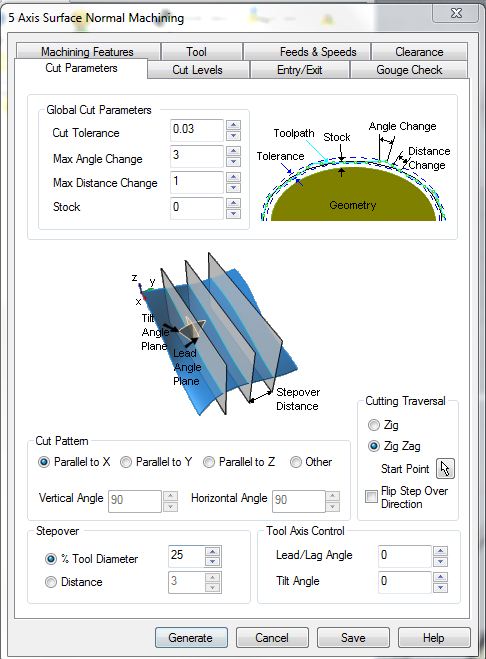
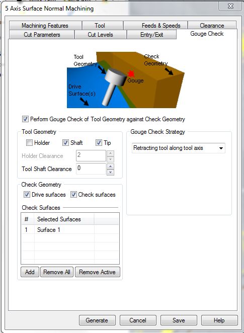
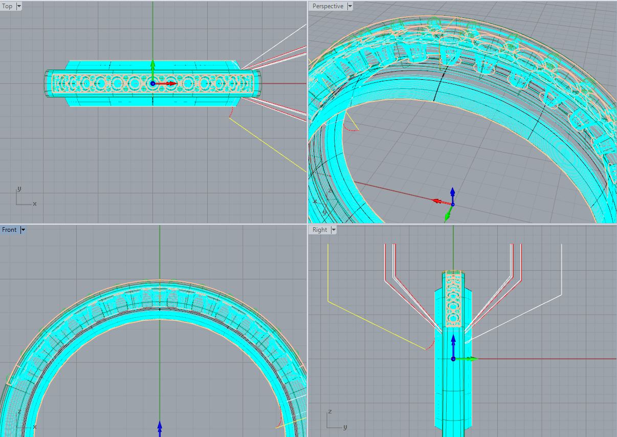
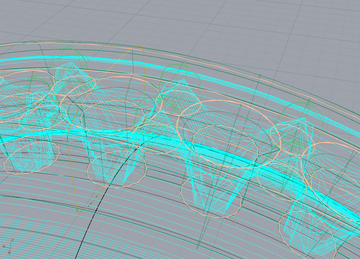
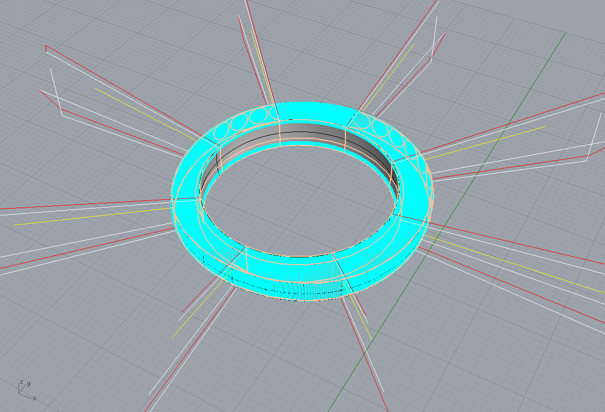
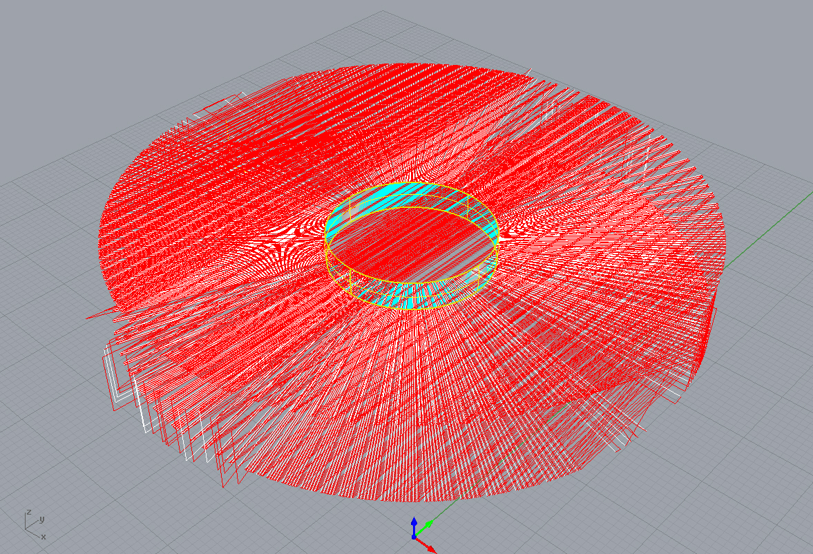
I tested this and I can create a surface at reasonable Z normal surface under my ring, which my machine can handle, and path a version of a rotary around the B axis using Surface Normal milling in 5X, and setting the ring as the gouge geometry.
this works as expected actually..
two snags the retraction method is UNDER the surface for soem reason and it very rough. Can gouge checking tolerance be improved to moved the tool tip over the surface.. then essentailly you have a rotary around B method that does not require multiple post processors?
images may help.
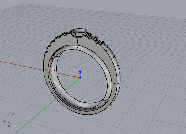
- ring and the surface for surface normal milling
- 1.jpg (139.75 KiB) Viewed 27535 times
- 2.JPG (69.46 KiB) Viewed 27535 times
- 3.JPG (58.75 KiB) Viewed 27535 times
Re: Setting up a Trunnion 5 axis
Posted: Thu Nov 06, 2014 3:49 pm
by Chris.Botha
- 4.JPG (177.56 KiB) Viewed 27531 times
- 5.jpg (1.38 MiB) Viewed 27531 times
Re: Setting up a Trunnion 5 axis
Posted: Mon Nov 10, 2014 6:19 pm
by MecSoft Support
Would you be able to upload the file or email it to
[email protected] so we could take a look it?
Re: Setting up a Trunnion 5 axis
Posted: Tue Nov 11, 2014 3:35 am
by Chris.Botha
Re: Setting up a Trunnion 5 axis
Posted: Wed Nov 12, 2014 9:13 am
by MecSoft Support
Hi Chris,
Real cool. This is how you use the drive surface and check against the gouge check surfaces in 5 axis. But we would still like to see why the toolpath is not smooth in the other model. So if you can send the model or something similar (if it is a proprietary model) to
[email protected] that would be great. Thanks.
Re: Setting up a Trunnion 5 axis
Posted: Wed Nov 12, 2014 12:32 pm
by Chris.Botha
no problem, ill dig it up.
that was done at work and didnt have my dongle with me so the path didnt actually save, but ill send the 3dm anywhow.
have partially resolved my rotary around B at home, but it isnt bug free, the method has insane amounts of retracts, which I cannot turn off from the builder. The retracts in the method are a longer path than the actual cut?
In DeskProto is an option to always stay low (ignore retracts) which is very handy. Ill screen grab the retract issue later, but by breaking up a fill circle into 8 segments and arranging them after each other the retractions seem to behave themselves.
my split method
- 8 sections.jpg (744.01 KiB) Viewed 27499 times
using one plane
- full.jpg (1.63 MiB) Viewed 27499 times
https://www.youtube.com/watch?v=sLyo4FFhVaw
i will email file to Uday later.
Re: Setting up a Trunnion 5 axis
Posted: Wed Nov 12, 2014 7:03 pm
by MecSoft Support
Thank you for emailing us the part file.
You would have to use 5 axis Flow Curve machining to program this part. Here is a screen shot of the toolpath for this operation.
Re: Setting up a Trunnion 5 axis
Posted: Wed Nov 12, 2014 7:31 pm
by Chris.Botha
you guys have the best support.. well done!
im back on track, I going seriously sideways

I should RTFM I guess?!?
https://www.youtube.com/watch?v=Sf4aHYWBJFA
Re: Setting up a Trunnion 5 axis
Posted: Sun Nov 16, 2014 2:03 am
by Chris.Botha
finally got her dialled in enough to test a cut.. X still WAY off but not bad!
Video of cut:
https://www.youtube.com/watch?feature=p ... TRY9VHbECI


Re: Setting up a Trunnion 5 axis
Posted: Fri Nov 21, 2014 8:26 pm
by Chris.Botha
we have liftoff!
https://www.youtube.com/watch?v=Pp1ENjXegEU
My only issue now is I cannot get the feeds and speeds to remember my speeds each time I open Rhinocam? It always defaults ot the ones when it was installed. I can load them from a file, but that interface does not actually allow me to save them to a file when i adjsut them?
Re: Setting up a Trunnion 5 axis
Posted: Mon Nov 24, 2014 4:47 pm
by MecSoft Support
When saving tools to library, selecting save as type as "Tools from knowledge base files (*.vkb)" will save tool & feeds/speeds to the library. Loading a tool library in (.vkb) format would load the tools with the feeds/speeds saved for each tool. RhinoCAM remembers the last loaded tool library and automatically loads this the next time you run RhinoCAM.
Re: Setting up a Trunnion 5 axis
Posted: Mon Nov 24, 2014 5:00 pm
by Chris.Botha
Awesome! Thanks Ill give that a go, my tool library is still from the original RhinoCam format, xml file i think.....