 Welcome to our 4-Part series on Hole Machining in 2 & 3 Axis CAM using MecSoft’s CAM plug-ins. The complete 4-part Guide is available to all AMS subscribers as part of your CAMJam Self-Training package. See How to Download your CAMJam Training Materials for information about CAMJam and how to reap the benefits of your AMS subscription!
In the third installment of our series we explore Automation techniques that will help you get your hole geometry programmed faster. This section includes Feature Detection, Feature Machining, How to set a default AFM Knowledge Base, how to machine from that Knowledge Base and how to add hole features to a new Knowledge Base of your own.
The following 4 blog articles are included in this series:
- Hole Machining in 2 & 3 Axis CAM Part 1: Geometry Selections
- Hole Machining in 2 & 3 Axis CAM Part 2: Cutting Parameters
- Hole Machining in 2 & 3 Axis CAM Part 3: Program Automation
- Hole Machining in 2 & 3 Axis CAM Part 4: Output Control
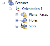
If the 3D model has hole features defined you can still use the selection techniques mentioned in Part 1: Hole Selection Techniques above. Alternatively you can use the feature detection tools on the Features tab of the Machining Objects Browser to detect your hole features.
Note that your part must be a polysurface solid model to use the Features tab options. You can set Diameter Range Filters from here also. Once hole features are identified, you can also manually execute a hole operation from the feature definition. First you need to detect your features.
Here are the basic steps to detect features:
1. Open the 3D polysurface solid model that contains hole features.
2. Select the Features tab from the Machining Objects Browser. If you do not see the Features tab, make sure the Machining Objects Browser is displayed. ![]() There is a toggle located to the left of the Program tab. Select it until the Machining Objects Browser displays.
There is a toggle located to the left of the Program tab. Select it until the Machining Objects Browser displays.

3. To set the diameter filter range, pick the ![]() Set Filters for Feature Detection icon to display the dialog.
Set Filters for Feature Detection icon to display the dialog.
4. From the Global Filters tab make sure the box for Holes is checked.

5. From the Hole Feature Detection Filters tab check the box to Use diameter filter and enter the minimum and maximum diameters to select. There is also a box to Include Partial Holes if needed. Now pick OK to close the dialog.

6. The first two icons on the Features tab will detect features. You must use one of these two icons. The first icon will perform ![]() Automatic Feature Detection (AFD). If you select it, ALL features in all orthographic orientation (not just holes) will be detected and added to your Features tree. They are also identified on your part geometry.
Automatic Feature Detection (AFD). If you select it, ALL features in all orthographic orientation (not just holes) will be detected and added to your Features tree. They are also identified on your part geometry.
 |  |
7. The second icon performs ![]() Interactive Feature Detection (IFD) and allows you to detect features only from a selected flat area. This would be similar to using the On Flat Areas selection technique mentioned in Part 1: Hole Selection Techniques except that ALL features detect on the flat area will be added to your Features tree, not just holes. The features are also identified on your part geometry.
Interactive Feature Detection (IFD) and allows you to detect features only from a selected flat area. This would be similar to using the On Flat Areas selection technique mentioned in Part 1: Hole Selection Techniques except that ALL features detect on the flat area will be added to your Features tree, not just holes. The features are also identified on your part geometry.
 |  |
 |
Hole Feature Types
The types of holes that are supported by AFM are any hole which has a cross-section that is made purely of straight line segments. In addition to this there cannot be any concave sections in the cross-section. The supported hole types are shown below.
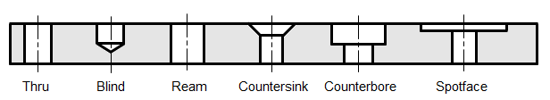
Note all of these holes have straight line cross-sections with no concavities. In addition to this, the segments that make up a hole’s cross-section can be classified as 3 distinct types.
1. Vertical
2. Horizontal
3. Angled
The Angled segment is a segment that makes an angle between 0 and 90 degrees to the vertical. That is 0 < angle < 90. The reason for these three distinctions is that each type of segment will be machined in a similar manner. Thus Vertical segments may be drilled, horizontal segments may be spot-faced and angled segments may be machined with a tool of a similar angle.
Hole Feature Cross-Section Rules
The following rules are applied when a detected hole feature’s cross-section varies from those found in the Default AFM Knowledge Base.![]() Rules when similar Hole Features are detected
Rules when similar Hole Features are detected
| Rules when a Similarity of Holes Diameters are encountered during AFM | ||
Hole Types Supported | ||
| Hole Pocketing & Profiling | |
If the tool is smaller than diameter | Create the operation with the same tool. | |
| If the tool is larger than diameter | Create the operation with the same tool but mark the operation as dirty. | |
| Countersink | |
If the tool is smaller than diameter & matches the chamfer angle | Create the program with the same tool. | |
All other cases | Create the operation with the same tool but mark the operation as dirty. | |
| Drilling | |
The tool matches the diameter exactly (within a user specified tolerance). | Create the operation with the same tool. | |
The tool is larger or smaller than the hole diameter. | Create the operation with the same tool but mark it as dirty. | |
| Spot Drilling | |
In all cases | Create the operation with the same tool but mark it as dirty. | |
| Spot Facing | |
In all cases | Create the operation with the same tool but mark it as dirty. | |
![]() Hole/Z Depth Rules when similar Hole Features are detected
Hole/Z Depth Rules when similar Hole Features are detected
| Rules when a Similarity of Hole Z Depths are encountered during AFM | |
 Hole Section Anatomy | |
Variation | Conditions & Rules |
| Condition: Start Z position is at start of a segment. Z Depth spans an entire section. |
Rule: Map start Z position to start of similar segment. Map Z depth to the entire depth of similar segment. | |
| Condition: Start Z position is at start of a segment. Z Depth spans multiple sections. |
Rule: Map start Z position to start of similar segment. Map Z depth to span all similar segments. | |
| Condition: Start Z position is at start of a segment. Z Depth is smaller than the same segment height. |
Rule: Map start Z position to start of similar segment. Map Z depth to a value computed as a ratio of the Z heights of the similar segments. | |
| Condition: End Z position is at end of a segment. Z Depth is smaller than the same segment height. |
Rule: Map end Z position to end of similar segment. Map Z depth to a value computed as a ratio of the Z heights of the similar segments. | |
| Condition: Both Start and End Z positions are between the start and end of a segment. |
Rule: Map start and end Z positions to values computed as a ratio of the Z heights of the similar segments. | |
| Condition: Start Z position is at start of a segment. End Z position is between another segment. |
Rule: Map start Z position to start of similar segment. | |
| Condition: Start Z position is between a segment. End Z position is at the end of a segment. |
Rule: Map start Z position to a value computed as a ratio of the Z heights of the similar segments where the Z height starts. | |
| Condition: Start Z position is between a segment. End Z position is also between a segment. |
Rule: Map start Z position to a value computed as a ratio of the Z heights of the similar segments where the Z height starts. | |
| Condition: Completely dissimilar holes are found. |
Rule: The system will ignore the operations and have a status message (or error message) stating that some KB operations were not applied. | |


Listing Hole Features
Once all of your hole features are detected they can be listed. Here is the procedure to obtain your hole feature list:
1. Open the 3D polysurface solid model file with hole features defined.
2. Detect your hole features. The procedure to do this is explained above. See Selecting Holes on a 3D solid model with hole features.
3. Once your hole features are listed in the Features tree, select the ![]() List Features icon from the Features toolbar.
List Features icon from the Features toolbar.
4. All of your features will displayed in the Machining Features Information table. The table will include information on Feature Type, Feature Name, and Feature Parameters. The Parameters column will contain the hole depth and minimum and maximum diameter dimensions. A Print button is provided if you with to print and save your list.

Machining Hole Features
You can only machine hole features AFTER the features are detected in your 3D solid model. See Detecting Hole Features above for the basic procedure to do this. Once your hole features are detected, you can execute the required hole operation directly from the feature definition.
Here are basic steps to do this:
1. First detect your hole features so that they are listed in the Features tree. The features tree is located in the Machining Objects Browser when the Features tab is selected.

2. Then right-click on a hole feature listed in the Features tree and select from the context menu of compatible toolpath operations. Only the operations that can be performed in the selected feature are listed in the menu.

3. Similarly, you can right-click on a hole feature that is detected and identified on your part model. By “identified” we mean that feature detection was performed and the hole feature displayed on your part model when you move the cursor over it.

4. If you do not see the feature highlighted, go to the Features section of the CAM Preferences dialog and make sure the box is checked to Turn on preselection highlighting. Also check the box to Turn on pre-selection information tooltips.

5. When the selected toolpath operation is executed, the hole feature information is automatically populated into the Hole Features tab of the toolpath operation dialog.
6. Complete the remaining tabs in the toolpath operation dialog and then select the Generate button to calculate and display the toolpath.
Set the Default AFM Knowledge Base
Before you can perform any Automatic Feature Machining (AFM) you should first check to make sure the correct AFM knowledge base is set. You can do this from the CAM Preferences dialog.
1. From the Machining Objects Browser select the CAM Preferences icon. It’s located on the top right end of the Machining Browser, next to the Help icon.

2. From the dialog select Features from the left side dialog menu.
3. Under the Automatic Feature Machining (AFM) Knowledge Base section locate the data field. It should show the folder location and file name of the AFM knowledge base.

Example: C:\ProgramData\MecSoft Corporation\RhinoCAM 20xx for Rhino x.0\FeatureBasedMachiningKBs\DefaultAFM_INCH.vkb
This example is pointing to the location of the default AFM knowledge base in inches for RhinoCAM. There is a similar file and location for VisualCAD/CAM, VisualCAM for SOLIDWORKS and AlibreCAM.
4. If the incorrect folder and/or file name is listed, select the “…” button to the right of the field to display the file browser.
5. Browse to the correct folder, select the DefaultAFM_INCH.vkb file and pick Open. If you work in metric units select the DefaultAFM_MM.vkb file and pick Open.
6. Now pick OK to close the CAM Preferences dialog.
Perform Hole Machining from a Knowledge Base
Here are the basic steps to automate hole machining using the default hole machining knowledge base:
1. First detect your hole features so that they are listed in the Features tree folder. The folder is located in the Machining Objects Browser when the Features tab is selected.
2. Then right-click on a hole feature listed in the Features tree and select Automatic Feature Machining (AFM) from the context menu. Alternately you can select the ![]() Automatic Feature Machining (AFM) icon located on the Features tab toolbar.
Automatic Feature Machining (AFM) icon located on the Features tab toolbar.
3. You can perform the same procedure when you right-click on a detected hole feature directly from the 3D part model.

If you do not see the feature highlighted on the part, go to the Features section of the CAM Preferences dialog and make sure the box is checked to Turn on preselection highlighting. Also check the box to Turn on pre-selection information tooltips.

4. A Hole Feature MOpSet is added to the active setup in the Machining Job tree of the Machining Browser. If a hole feature match is found in the default hole machining knowledge base the machining operation created is generated automatically.

5. If the Hole Feature MOpSet created in the Machining Job is flagged, this means that no match could be found in the current default AFM knowledge base.
6. If this occurs, expand the Hole Feature MOpSet folder, right-click on the toolpath operation and pick Edit.
7. Select a tool and check the parameters in each tab of the operation dialog and pick Generate. The flagged should disappear. If it does not, check your parameters and try again.
Add Hole Features to the Default AFM Knowledge Base
Hole features are stored in the default AFM knowledge based on the cross-section dimensions of the hole. If an exact match (all diameters and depths of the hole) is found in the knowledge base it is used. You can add hole feature MOpSets to the default AFM knowledge base.
Here are the basic steps to edit the default AFM knowledge base:
1. First make sure the default AFM knowledge base is set. See: Set the Default AFM Knowledge Base for the procedure to check this.
2. Load the part file that contains the 3D solid model of the hole feature,
3. Detect the hole features in the part. You can use either the Automatic Feature Detection (AFD) command or the Interactive Feature Detection (IFD) command. Both are located on the Features toolbar. See: Detecting Hole Features above for this procedure.
4. From the Features tree select and right-click on the hole feature that you want to add to the knowledge base. You can also right-click on the detected hole feature directly from the 3D part model. If you do not see the feature highlighted on the part, go to the Features section of the CAM Preferences dialog and make sure the box is checked to Turn on preselection highlighting. Also check the box to Turn on pre-selection information tooltips.
5. From the context menu that displays select ![]() Create Hole Feature for Machining KB. Alternatively, you can select the icon from the Features toolbar.
Create Hole Feature for Machining KB. Alternatively, you can select the icon from the Features toolbar.
6. This will display the Select/Load/Create Operations for Matching Hole Feature dialog. This dialog allows you to assemble a MOpSet of toolpath operations to associate with the selected hole feature. For reference a cross-section of the selected hole feature is displayed along with its dimensions.

7. On the left side of the dialog you will see a list of toolpath operations that are compatible with the hole feature you have selected. Your hole feature is listed on the right. Consider how you want to machine the hole feature and then Drag & Drop the toolpath operations from the left to the right. Hint: Select and drag the folder of the toolpath operation past the vertical dividing line and drop it. It will locate itself under your hole feature folder.
8. Once you have all of the toolpath operations dropped into your hole feature folder, you can Drag them up or down in the list.
Note: In this dialog you are creating the MOpSet that will be executed when a matching hole feature is found. So make sure you arrange the toolpath operations in the order that you want then executed. For example if your hole feature is a counter-bore hole you may want the following operations listed in your hole feature folder:
9. When you are satisfied with your hole feature MOpSet (machining operation set), you can select one of the save buttons located at the bottom of the dialog.
Create Hole Feature MOpSet: Adds the MOpSet directly to your Machining Job.
Save as Knowledge Base: Saves the MOpSet to a new knowledge base file.
Save in AFM Knowledge Base: Adds the MOpSet to the current default AFM knowledge base defined in the CAM Preferences dialog.
Save in Knowledge Base: Select this button to save the Hole Feature and its Desired Operations into an (AFM) Knowledge Base file that is not set as the Default (AFM) defined in the Features section of the CAM Preferences dialog.
Add Hole Features to a New AFM Knowledge Base
You can also create a new AFM Knowledge Base.
1. See: Add Hole Features to the Default AFM Knowledge Base above and complete steps 1-8.
2. Pick Save as Knowledge Base.
3. From the File Save As dialog navigate to the folder where you want to locate your knowledge base file. Enter a name for the knowledge base and pick Save.
For more information:
- Hole Machining in 2 & 3 Axis CAM Part 1: Geometry Selections
- Hole Machining in 2 & 3 Axis CAM Part 2: Cutting Parameters
- Hole Machining in 2 & 3 Axis CAM Part 3: Program Automation
- Hole Machining in 2 & 3 Axis CAM Part 4: Output Control


