 In most cases individual ring jewelry designs are produced in quantity by first creating a 1:1 scale Positive Master Wax Model representing the ring design. Multiple copies of this positive master wax model is then used to produce the actual ring jewelry in quantities using an investment casting process. The positive master wax models can be created from cavity molds or by direct machining of the wax material, depending on the quantities required. Example toolpath techniques for both processes are detailed below.
Watch the video at: https://youtu.be/BzZkfN6_4n0
Machining Mold Cavities for Master Wax Ring Models
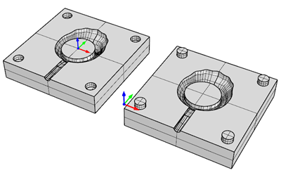
Shown below are the 2½ & 3 Axis toolpath techniques used to machine one side of a single cavity mold. The mold is used to produce a positive wax model of a contoured ring design. The ring design is symmetrical so the opposite cavity side of the mold is identical except for the alignment pins and runner. In this example, both sides of the mold are in the same CAD file, but on different layers. Here is what the CAD file looks like along with the Machining Job Tree. While there is only one Setup, each cavity side has its own MOp Set of toolpath operations, each preceded by a Work Zero.
 |
 |
Below we see the sequence of toolpaths and techniques used to machine the first MOp Set in the Machining Job. On the left, the mold cavity and each toolpath is shown with the Control Geometry for the operation highlighted. The resulting cut material simulation is shown on the right. Let’s have a look:
About the Techniques Used:
- Notice that the first toolpath, 2½ Axis Roughing, is used as a finishing operation to machine the pins and clear the parting plane of material. This is achieved by setting Stock to zero, the Cut Pattern to Offset and on the Cut Levels tab, checking Clear Flats and setting Bottom (B) value to -2.5 which is at the parting plane Z depth.
- Notice the sequence of 3 Axis finishing toolpaths using the taper mill. Horizontal Finishing, followed by Parallel Finishing, followed by Pencil Tracing in combination provides complete finishing of the ring contour.
 |
 |
|
Contoured 3 Axis Ring Cavity Block, Side A, Stock: 50 x 50 x 12.5 |
|
 |
 |
|
2½ Axis Roughing, Tool: 3.175 Flat Mill, Stock: 0, Pattern: Offset, Stepover: 25%, Cut Levels: 50%, Clear Flats: ON, Bottom: -2.5 (at Cavity Parting Line) |
|
 |
 |
|
3 Axis Horizontal Roughing, Tool: 3.175 Flat Mill, Stock: 0.1, Pattern: Offset, Stepover: 25%, Cut Levels: 20%, , Top: -2.5 (at Cavity Parting Line) |
|
 |
 |
|
3 Axis Horizontal Re-Roughing, Tool: 1.587 Flat Mill, Stock: 0.1, Pattern: Offset, Stepover: 25%, Cut Levels: 40% |
|
 |
 |
|
3 Axis Horizontal Finishing, Tool: 0.5 x 2 Deg Taper Mill, Stock: 0, Cut Levels: 0.1 |
|
 |
 |
| 3 Axis Parallel Finishing, Tool: 0.5 x 2 Deg Taper Mill, Stock: 0, Stepover: 15% | |
 |
 |
| 3 Axis Pencil Tracing, Tool: 0.5 x 2 Deg Taper Mill, Stock: 0 | |
Direct Machining of Master Wax Ring Models
In this section we look at techniques of machining the master wax ring model directly from a wax stock block. The challenge in direct machining is holding the part being machined so that all features can be machined. Special jigs or fixtures have to be employed to help in holding the part during machining. These special fixtures can be obtained from various manufacturers of CNC machines dedicated to machining for jewelry.
Indexed 4 Axis (Flip) Machining Methods
Shown below are the 2½ & 3 Axis toolpath techniques and rotary indexing operations used to machine two sides of a positive master wax model of the ring design. A rotary jig fixture is used to hold the stock material in place during machining. Note that the Professional configuration of the milling module is required for this process. Here is what the CAD file looks like along with the Machining Job Tree. The Machine is set to 4 Axis using a Box Stock of the required dimensions to fit within the fixture. Setups 2, 3 & 4 rotate the table 180 degrees as needed to complete the 2-sided machining process.
 |
 |
Below we see the sequence of toolpaths and techniques used to machine the first MOp Set in the Machining Job. On the left, the mold cavity and each toolpath is shown with the Control Geometry for the operation highlighted. The resulting cut material simulation is shown on the right. Let’s have a look:
About the Techniques Used:
- It is important to understand the position of the rotary axis defined by each setup. In Setup 1, the Rotary Axis is set to 0 Degrees (default). In Setup 2, the Rotary Axis is rotated by 180 Degrees. In Setup 3, the Rotary Axis is rotated back to 0 Degrees.
- Notice the use of the planar curves as Control Geometry used to contain the cutting to only the desired areas. The larger rectangle contains the 3 Axis Horizontal Roughing toolpath. The smaller circle and offset curve contain the 3 Axis Radia Finishing toolpaths (to cut only between these two curve regions.
- Notice the addition of the center jig block containing 3 holes. These will serve to mount the in-process ring stock onto the 4 Axis bar extending out from the right end of the fixture. These allow the in-process part to mounted for the continuous 4th Axis Parallel Finishing toolpath.
- Notice that four (4) tabs were modeled that serve to anchor the part to the remaining stock during machining. They lie on the center plane and extend from the center jig block through the part and extend past the outer containment rectangle. These form a connection bridge that keeps the part connected and stable during machining. They are removed manually after machining.


