The content for this article comes to us courtesy of David St. Angelo, CNC Programmer & Operator with Jim Thompson Marine Carpentry (JTMC), located at 1 Washington Street, Newport, RI the Newport Shipyard’s carpentry shop, specializing in Yacht Carpentry, Finishing, Furnishings and more.
Watch the companion video here!
Blog Contents:
- The Part
- Additional CAD Geometry
- Add Machining Regions
- The Stock & Setup
- Sequence of Operations
- Drilling Operations
- Roughing Operations
- Finishing Operations
- Polar Instancing
- Optional Methods
The Part
Note: All dimensions mentioned in this article are in millimeters (mm). This part is referred to as Viasat. It is used as a mounting bracket for a large satellite receiver on the top of a 90 foot catamaran. The CAD geometry for this project is a 375.0 diameter x 25.00 thick ring of T10 steel (very hard). Please refer to the illustrations below for reference. The ring contains 4 keyway slots that are 22.00 wide, 58.730 long and are positioned along a 142.42 center-line radius. So the length of each keyway slot is on a radius. Each keyway also contains a stepped counterbore. The full 22.00 wide keyway drops down to 10.00 before narrowing to 11.96 wide. What makes this keyway feature very unique is that the base of the counterbore ramps downward 5 degrees on each side. You can refer to the elevation images below for more details.

|
What makes this keyway feature very unique is that the base of the counterbore ramps downward 5 degrees on each side. The elevation view below shows a cross section of the ramp clearly. The length of the ramp is approximately 16.00 long. The ramp also occurs on both sides of the keyway. |
 |
 |
| (Left) A cross-section view of the 5 degree ramped counterbore portion of the keyway. (Right) An isometric view of the keyway showing the portion of the counterbore that is ramped downward 5 degrees. | |
Additional CAD Geometry

In many machining strategies you will want to add reference geometry that will help guide your toolpaths. In this example we are adding the two curves shown in the illustration here labeled Inner Curve and Outer Curve. We created these two curves by (1) creating curves that are offset inward from the base of the counterbore (this is the 10.00 depth dimension shown above). These curves define the 5 degree ramp angle. (2) We then joined and trimmed these new curves into just two curves, one inner curve and one outer curve. After that (3) we added another half circle curve of radius 3.905 positioned on the outer curve at the end closest to the thru hole. This half circle curve is labeled “Radius for Engraving” in the illustration. We have also added a geometry point located at the top of the 22.00 thru hole. This point is labeled Start Point for Roughing in the illustration. As described, this point will be used as the cut start point for a 3 Axis Roughing operation.
Let’s review:
- We created curves that are offset from the base of the keyway inward by a distance of 3.905 which is the radius of the flat end mill tool we plan to use.
- We then merged and trimmed these curves to form just two curves, one inner curve and one outer curve.
- We also added a new curve that is a half circle and located it at the end of the outer curve closest to the thru hole.
- These curves will drive the center tip of the tool during a 2½ Axis Engraving operation.
Add Machining Regions
In this step we will create 4 pre-defined machining regions. MecSoft CAM allows you to create machining regions and save them for use with toolpath operations. In this example we will predefine 4 machining regions. We will use these regions to drive our cutting tool during a 2½ Axis Engraving toolpath operation. See Finishing Operations below for more about how these predefined regions are used. Also refer to the Optional Methods section below. You will also find suggestions on alternate methods to achieve the same goal.
When we are finished creating the predefined regions, the Regions tab of the Machining Objects Browser will look like the image below. We see that there is one Machining Region Set: Radial Slot that contains 4 regions below it. These 4 regions are named Slot Top, Slot Bottom, Slot Ramp Outer and Slot Ramp Inner.

The toolbar on the Regions tab contains the icons and commands you need to create the region set and the four regions. These are the first two icons on the left side of the toolbar. The first being the Create Machining Region Set command. Selecting it adds a new set with nothing under it. Then when you pick the Select Curves icon, you are prompted to select curves. So we selected the top edges of the keyway slot and pressed enter. A region named “Curve Region #” is added under the region set. If you create the region first, the region set is added automatically. We then renamed this region as Slot Top.

Slot Top |

Slot Bottom |

Slot Ramp Outer |

Slot Ramp Inner |
We repeated this procedure to create a region named Slot Bottom. We then created the two regions named Slot Ramp Outer and Slot Ramp Inner. You can also select all of the 4 curves at one time and add each to the set and then rename them. Now when you select each region from the Regions tab you see that they highlight green on the part. The illustrations above show you what each region looks like.
The Stock & Setup
The stock definition for this project is a Part Bound Cylinder Stock. It is referred to as Part Cylinder Stock on the Stock menu on the Program tab. This stock definition computes the size of your part and then allows you to add an offset value to both the Radial and the Axial dimensions. You can also set the axis of the cylinder and the Axial Offset Direction. In our case we selected the Z axis, set the Radial Offset (r) to 5, the Axial Offset (a) to zero. Since we set the Axial Offset (a) to zero, we need not bother with setting the Axial Offset Direction as it will be ignored. Also, to make sure only the 3D solid was calculated, we checked the box to Ignore Wireframe Geometry in Bounds Computation. The stock and stock dialog are shown below.

Sequence of Operations
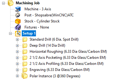
The Machining Job and Setup 1 shown below includes two Drilling operations, one 3 Axis operation and three 2½ Axis operations. Note that the 2½ Axis Engraving operation cuts the 5 degree ramp and is the next to the last operation in the Machining Job. The last operation is the Polar Instance that will cut the remaining 3 keyway slots automatically. Also refer to the Optional Methods section below. You will find suggestions on alternate methods in this operational sequence.
|
|
|

Drilling Operations
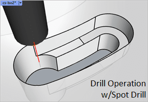
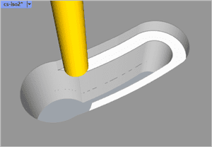
We have used Drilling as the first two operations. These will spot drill (referred to as a Center Drill) a 6mm x 1mm deep hole followed by a Deep Drill to drill a 14mm dia hole through the part at 5mm step increments. The Add Tooltip to Drill Depth option is checked to make sure the drill passes completely through the part. These two drilling operations are illustrated at (A-1 & A-2) and (B1 & B2) in the table below. The toolpath is shown on the left and the resulting cut material simulation is shown on the right. Both drilling operations are located at the Point geometry that we added at the top of the 22 diameter through hole on the keyway.
|
|
|


|
|
|


Roughing Operations

The next two operations in the Machining Job are considered roughing operations. They are a 3 Axis Horizontal Roughing and a 2½ Axis Pocketing operation. The 3 Axis Horizontal Roughing is used to rough cut the upper counterbore level of the keyway. For the Control Geometry tab we are picking the Select Predefined Regions button to display the Select Predefined Region(s) dialog shown here. Selecting Slot Top and picking OK, assigns that region to this operation.
For the Cut Parameters tab, Stock is set to 0.5, an Offset cut pattern, Mixed cut direction and a 25% (of the tool diameter) stepover. On the Cut Levels tab the Stepdown is set to 2 levels and the Bottom (B) under Cut Levels is set to -10.84 which is the bottom of the 5 degree ramp. The engage and retract are set to helix motions. This toolpath and resulting cut material is shown at (C-1 & C-2) below. It should be noted here that David wants to use the same cutter for all milling operations.
|
|
|


The next operation in the Machining Job is 2½ Axis Pocketing. You can see the toolpath and the cut material simulation at (D-1 & D-2) below. For the Control geometry tab, we are using a predefined region in the same manner as we did above for the 3 Axis Horizontal Roughing. This time however, we have selected the Slot Bottom region. Also from the Control Geometry tab we have selected the Start Points sub-tab and then picked the Select Start Points button to add the point geometry we modeled to this operation (see CAD Geometry above). This will force the cutting to start at the top of our predefined thru hole location.
This is considered a roughing operation because on the Cut Parameters tab we have Stock set to 0.2. This will leave 0.2 of material around the side walls of the bottom level of the keyway. Other cut parameters include an Offset cut pattern, a Mixed cut direction, and a stepover of 25%.
|
|
|

Finishing Operations
The remaining two operations in the Machining Job are considered finishing operations. They are a 2½ Axis Profiling and a 2½ Axis Engraving operation. The 2½ Axis Profiling MOp is used to finish the side walls of the bottom level of the keyway slot. The Control Geometry tab of this operation is assigned the same pre-defined region (Slot Bottom) as the previous 2½ Axis Pocketing operation.
For Cut Parameters the Tolerance is set to 0.01 and Stock is set to zero and Cut Direction is set to Mixed. For Cutting Side, the Determine using 3D Model is checked. The option Use Mid-Point of Longest Side is also checked which will move the start point to the our pre-drilled thru hole location. For the Cut Levels tab, the Location of Cut Geometry is set to At Bottom and the Total Cut Depth, Rough Depth, Finish Depth, Rough Depth/Cut and Finish Depth/Cut are all set to zero. This will produce one cutting pass at the bottom of the keyway slot. You can see the toolpath and the cut material simulation at (E-1 & E-2) below.
|
|
|


The final finishing operation is the 2½ Axis Engraving. This operation completes the keyway slot by machining the 5 degree ramp and finishing the side walls of the upper counterbore at the same time. From the Control Geometry tab we have selected the remaining two predefined regions. Also note the order of the regions in the Control Geometry tab. The Slot Ramp Outer region is listed first. This region will control the location of the tool at the cut start point. The Slot Ramp Inner region is listed second.

When the cutter reaches the end point of Ramp Slot Outer it will immediately continue cutting from the start point of Slot Ramp Inner and then proceed to its end point to complete the operation. You can see the toolpath and the cut material simulation at (F-1 & F-2) below.
In 2½ Axis Engraving the center tip of the cutting tool (6.33 Diameter Glass/Carbon 46264 Flat End Mill) will follow the assigned control geometry exactly. In this case the predefined regions that we have created are driving the cutter to produce the finish cut of the 5 degree ramp at the base of the counterbore (on each side)!
|
|
|


The Cut Parameters tab simply states that the Tolerance is 0.01, the Cut Direction is Natural (meaning it is following the direction of the predefined regions), Location of Cut Geometry is At Bottom, all Cut Depth Control values are set to zero (one pass). For entry and exit both are set to None. From the Advanced Cut Parameters tab, Arc Fitting tolerance is set to 0.02.
Polar Instancing
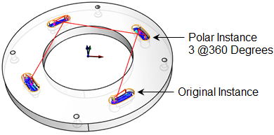
The last item in the Machining Job tree is called Polar Instance 3@360 Degrees. As the name suggests this folder contains a copy of the six operations described above and defines the polar instance for the remaining three keyway slots. David can generate the gcode needed for all 4 keyway slots by simply posting out the Polar Instance.
Optional Methods
As we all know there are different approaches and methods to complete any CAM project. You may have already thought of a few while reading this article. We have to and would like to share a few of them with you here.
- Use native CAD system Curves instead of Curve Regions:
In the Add Machining Regions section above we used MecSoft CAM regions derived from the native CAD system’s curve geometry. There is a reason for this. (a) We wanted to show you how to use Regions. (b) At times it can be easier to define, edit and select Regions rather than rely on the native CAD system to do this.
However, we could have skipped the Add Machining Regions section, and simply selected the native curves as Control Geometry. However, we would have needed to make sure the curve start points are correct. In RhinoCAM you can use the Mark Curve Start command (CrvStart) to do this. In VisualCAD/CAM you would use the Reverse Curve Direction command located on the Curve Modeling tab if the curve start point is incorrect. - Use 3 Axis Parallel Finishing instead of 2 Axis Engraving: We could have used the 3 Axis Parallel Finishing method but would have had to settle for less control of the cutter. Again, in 2½ Axis Engraving, the tip of the cutter follows the control geometry (i.e., the curve regions) exactly. There is no greater control than this.
- Reverse the direction of Slot Ramp Inner:
If you look closely at the illustration below, you will notice that the start point of the Slot Ramp Inner predefined region is located at the end point of Slot Ramp Outer causing the cutter to ramp downward, cutting with the flat bottom of the cutter during the 2½ Axis Engraving operation. This is not ideal. If we reverse the direction of this curve region, the cutter will ramp upward, allowing the tool to cut along it’s flute length.

Cool Project David!Thank you for allowing us to showcase your work at Jim Thompson Marine Carpentry!
|

More about Jim Thompson Marine Carpentry
From new decks to custom cabinetry, Newport Shipyard’s carpentry shop, managed by J. Thompson Marine Carpentry, produces the highest quality woodwork on every new build and refit. All carpenters and craftsmen are versed in the widest range of materials, methods and technologies, be it wood, Corian, or composite from new to classic yacht restoration. The right fit and finish is a constant at Newport Shipyard!
 |
 |
 |
 |
 |
 |
Newport Shipyard’s carpentry shop, managed by J. Thompson Marine Carpentry


