RhinoCAM’s Programmable Post-Processor

Search

Blog Categories

For David and his team at Composite Solutions, MecSoft developed a programmable postprocessor for their Aggregate Drill Block machining applications. With this development, MecSoft has again demonstrated the flexibility and adaptability of its newly developed programmable post technology. This technology, introduced in our 2022 CAM product, uses the Python programming language and an event-driven model that allows you to handle complex and precise logical operations during post-processing. 

What is a Python Script?

A Python Script, the file containing the commands, is structured to be executed like a program. These files are designed to contain various functions and import various modules. Python interactive shell or the respective command line is used to execute the script, to perform a specific task.

How Programmable Post-processing in RhinoCAM Works

Each programmable post-processor is driven by a dedicated Python Script developed by MecSoft Corporation for a specific end-user application. The development effort typically involves a collaborative effort between MecSoft and its end user.

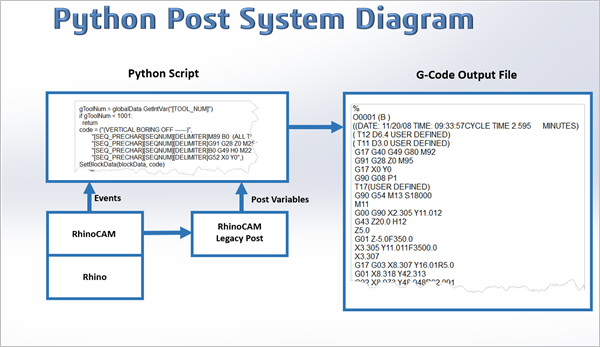
If you refer to the flow diagram below you see that the Python script (i.e., the Programmable Post) is triggered by events emanating from the RhinoCAM Machining Job. This “event Information” includes all setup and toolpath data and the sequence, or “events” as they occur during the Machining Job. Even more importantly, the Python script has access to all RhinoCAM post-processor variables defined in a companion SPM (legacy) post-processor file.

These variable values are populated by RhinoCAM during post-processing and are derived from and are unique to each Machining Operation in the Machining Job being post-processed.
In this system diagram, we see how the Programmable Post Python Script and its interface to the various RhinoCAM sub-systems are involved in event-driven CNC post-processing.
The system diagram above shows the Programmable Post Python Script and its interface to the various RhinoCAM sub-systems involved in post-processing. The Python post not only interfaces with the RhinoCAM system running inside Rhino but is also fully aware of all the post-processing variables populated in the legacy SPM post. During the Post-Processing process, RhinoCAM cycles through each Machining Operation found inside the Machining Job and iterates through the computed toolpaths. During this iteration, as events such as Program Start, Tool Change, etc. are encountered, RhinoCAM calls the corresponding event processor, if defined, in the Python script. The event processing method in the Python script can then perform any mathematical or logic function that the event handler method has been programmed with.

Some Example Uses for Programmable Posts

MecSoft’s Programmable Post technology can be leveraged for any shop floor CAM situation that requires specialized g-code output that was not handled by the older generation legacy post-processors. In addition to this, you can utilize the power of the Python programming language and implement specific Logic, Looping, Conditional Branching, etc. to handle almost any situation that a machine controller might require. Here are just a few examples.

Output in Polar Coordinates

An example of where a Python Programmable post was utilized at a customer site was to convert the XYZ coordinates of the toolpath to polar coordinates that a specialized optical machine needed as input. The logic of this conversion was programmed in a Python script.

Custom Feed Rate Controls

This allows you better control of cut feeds during specific machining events. Currently, in RhinoCAM, cut feed rates can be applied to a specific tool or a specific machining operation. These feed rates are set BEFORE the operation is generated and do not change. However, using a Programmable Post-processor, cut feed rates can be controlled during the course of the machining job based on any number of variables such as the trajectory of cut, depth of cut, tool radius, etc.

Custom Output of Information

Currently, in RhinoCAM, there are specific locations where the user can insert customized information in the form of comments. You can add comments to a cutting tool that will be inserted into the posted g-code when that tool is called during a tool change. You can also include the complete tool list at the start of the posted g-code. The format of the tool list is set by RhinoCAM and cannot be changed. However, using a Programmable Post-processor, you have nearly unlimited control of how the tool list is formatted and where the tool list information is located in the posted g-code file.

Drill Blocks and Programmable Posts

Utilizing MecSoft’s development team and RhinoCAM Programmable Post technology, David Gunn and Composite Solutions are able to produce custom g-code to operate an aggregate Drill Block attachment for their Anderson Selexx and Excitech CNC 4×8 routers. In the Programmable Post Drill Block project, MecSoft Corporation and Composite Solutions teamed up.

What is an Aggregate Drill Block?

An aggregate or angle head is a device that is attached to the spindle drive of a CNC machine to allow the user to route or drill at different angles other than where the spindle is orientated. A Drill Block is a specialized aggregate with multiple sub-spindles, each containing a drilling tool.
What is an Aggregate Drill Block?

How the Drill Block Programmable Post Works

A typical CNC machine during processing a G-code file, when encountering a tool number, the machine retrieves that tool from an Automatic Tool Changer and begins cutting. Each cutting tool is identified by the number assigned to it by the tool changer. If the tool changer holds 10 tools, then each position in the changer is numbered 1 thru 10. Then, for example, the tool that is located in position 4 becomes Tool Number 4. If the CNC does not have an Automatic Tool Changer, then the tool is always Tool Number 1.

Why are Cutting Tools Numbered?

In a default CNC application, cutting tools such as face mills, end mills, tapered mills, drills, etc. are assigned specific tool numbers. Many CNC machines include Automatic Tool Changers which is a turret system that holds multiple tools.
For Composite Solutions, the tools to engage in the Drill Block are also controlled by the Tool Number called for by the Drill machining operation. So to drill holes using the Drill Block, a normal Drill machining operation is created. However, the specific tools to engage in the drill block are encoded into the tool number by the CAM user using a formula as described below.

How the Drill Block is Programmed

The CAM user first computes the encoding value (a number) necessary to define which drill tool spindles in the Drill Block are needed to be activated for a given operation. This encoded number is then saved as the tool number of the tool used in the Drill machining operation used to control the Drill Block. This tool number is then decoded by the Programmable Post during post-processing to insert the appropriate G-codes to turn on the desired drill tool spindles. This process is explained in the sections below in more detail.

Description of the Drill Block

Add Your Heading Text Here

The illustration here on the right shows the Drill Block in relation to the main spindle. It shows the identification of each Drill Tool Position. We use the term Tool Position so that you do not confuse them with Tool Numbers.
There are 5 Tool Positions in the X direction and 5 Tool Positions in the Y direction, for a total of 9 Tool Positions. In this Drill Block, only the spindles along one axis can be active at one time. That is, a spindle along the Y axis cannot be turned on at the same time a spindle along the X axis is on. Note also the Tool Position values can take one of these 5 values: 1, 2, 4,8, and 16. These can be considered binary numbers and programmers will be familiar with this.

Encoding the Tool Positions in RhinoCAM

To encode which set of Tool Positions to activate for a specific Drill operation, the RhinoCAM user goes by a simple formula.

For the Tool Positions along the X axis, simply add up the Tool Position values and add this sum to 1000. As an example, if you want to activate Tool Positions B4 and B16 (see illustration above), the formula to encode this information is:

( 4 + 16 ) + 1000 = 1020

For the Tool Positions along the Y axis, a similar formula applies. Simply add up the Tool Position values and add this sum to 2000. So for instance, if you want to activate Tool Positions B2 and B8, then the formula becomes

( 2 + 8 ) + 2000 = 2010

Programming the use of the Drill Bank in RhinoCAM

In RhinoCAM if you want to use the Drill Bank in a machining operation, these are the steps to follow:

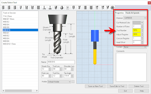
4. Create a regular drilling operation and select the point to the machine to be in the location where you would want the B1* tool position to be when machining.

5. Encode the Tool Position number value and use this value as the Tool Number** of the drill tool used in the machining operation.

6. Once the toolpath is created, then post-process using the specialized Programmable Post written specifically to handle this drill bank.

* Note that Tool Position B1 is shared by both X and Y directions, and only spindles along one axis can be activated at one time. This is by design.

**The 1000 and 2000 values are used to increase the tool number to a value that is out of the range of typical use. This assumes that a typically assigned tool number would be well below T1000. 

How the Tool Numbers appear in RhinoCAM

Using the encoding formulas described above, the RhinoCAM user calculates what the tool number needs to be in order to activate the required drills in the Drill Block. In the dialog examples below you see that for the drilling operation named M88 B16: 3mm, the required tool number is 1016.
Here we see the Tool definition dialog. The Tool Name is M88 B16 and the Tool Number and Adjust register are both 1016.
Here we see the Machining Job on the left with the Drill operation named M88 B16: 3mm expanded to show that the tool named M88 B16 is used.  On the right, we see the Tool tab of the Drill operation.

How the Drill Block is Decoded

When RhinoCAM encounters a tool change in the Machining Operation, it will trigger an OnToolChange() event and call the event processing method in the Python script.  This event processing method is shown below:
# Process Tool Change
def OnToolChange(blockData: PostBlockData, globalData: PostGlobalData):
  global gOP_TYPE, gToolNum
  # Skip if not a hole operation
  gToolNum = globalData.GetIntVar(“[TOOL_NUM]”)
  # Get block code
  blockCode = GenerateToolChangeBlock(blockData, globalData)
  SetBlockData(blockData, blockCode)
  return
Here we see the portion of the Python script that processes the OnToolChange() event.
You may notice that this event calls an additional method called GenerateToolChangeBloc() which actually does the heavy lifting. This method is what does the decoding of the intelligence encoded into the tool number of the Machining Operation and performs conditional formatting of the g-code output. This logic is shown below:
# Function to generate output code for tool change 
def GenerateToolChangeBlock(blockData: PostBlockData, globalData: PostGlobalData):
  global gOP_TYPE, gToolNum
  newline = “\n[SEQ_PRECHAR][SEQNUM][DELIMITER]”
  drillZ = “G43 H30 Z100.”
  if gToolNum > 2000:
    bToolNum = gToolNum – 2000
    code = “[SEQ_PRECHAR][SEQNUM][DELIMITER]M89 B”
    code = code + str(bToolNum) 
  elif gToolNum > 1000:
    bToolNum = gToolNum – 1000
    code = “[SEQ_PRECHAR][SEQNUM][DELIMITER]M88 B”
    code = code + str(bToolNum)
  elif gToolNum < 1001:
    bToolNum = gToolNum
    code = code + str(bToolNum)  return code + drillZ
Here we see the logic portion of the Python script that decodes the intelligence that the RhinoCAM user encoded into the tool number of the Machining Operation.:
As you can see, if the tool number is between 1001 and 2000 the M88 statement is formatted.  Similarly, if the tool number is greater than 2000 the M89 statement is formatted.  The M88 engages the spindles along the X axis and the M89 engages the spindles along the Y axis, as explained in the above section titled How the Drill Block Programmable Post Works.

This formatted output will then be written to the posted G-code file (shown below), directing the CNC machine to utilize the Drill Block as the RhinoCAM user intended.  Note that the g-code sample below is ONLY for the operation in the Machining Job named M88 B16:3mm.
%
O0
G17 G40 G49 G80 M92
G91 G28 Z0 M95
G17 X0 Y0
G90 G08 P1 (VERTICAL BORING ON —-)
G90 G54M23 (NO 2 SPINDLE ON)
(M88 B1: 10mm)
M88 B1
G52 X72.10 Y215.10 M21
G43 H30 Z100.
G00Z58.
X2302.979Y-835.343
Z2.5
G01Z-3.F1200.
Z2.5F9000.
G00Z58.
(VERTICAL BORING OFF ——)
M89 B0  (ALL TOOLS UP)
G91 G28 Z0 M25 (NO 2 SPINDLE OFF)
B0 G49 H0 M22  (NO 2 SPINDLE UP)
G52 X0 Y0
G00 G28 G91 Z0 M15
M12
 G90 X0. Y420.
G49 G90
G08 P0
M30
%

Here we see an example of the posted G-Code utilizing the RhinoCAM Programmable Post. This is the G-Code output when the machining operation named “M88 B16: 3mm” is posted.  

Example Rhino design drawing of a typical flat-pack sheet. The RhinoCAM Machining Browser and Machining Objects Browser are shown parked on the left side of the Rhino display.

More Pics from Composite Solutions

unnamed (1)

David and Tina Gunn are hard at work in the Composite Solutions shop!

Production sheets right off the Selexx 4 x 8 router at Composite Solutions. RhinoCAM automatically places Bridges & Tabs to help keep the stock stabilized during machining.

cs-cnc-metal2

Here on the left, we see more machined sheet products. On the right, we see the spindle (behind the brush guard) and the automatic tool changer on the Excitech CNC 4×8 router.

Need a Programmable Post-Processor?

To get your programmable post-processor off the ground, drop our sales team an email at [email protected] to get the ball rolling!

From the blog

The latest industry news, interviews, technologies, and resources.
Don LaCourse

Don LaCourse

Don LaCourse is an Application Engineer with MecSoft Corporation. Don brings over 20 years of experience in CAD/CAM operations in both automotive and mold design applications. Don also has extensive experience in documenting CAD/CAM products and is actively involved with writing the on-line help as well as creating training tutorials for MecSoft's products.

Try us out,

no strings attached!

Download Demo Form

Name(Required)
Product of Interest(Required)
This field is for validation purposes and should be left unchanged.

Name(Required)
Product of Interest(Required)
This field is for validation purposes and should be left unchanged.