 I want to take a moment to touch base on another topic related to our previous post Understanding Cut Levels in 2½ Axis Machining. I invite everyone to go back and review this informative post. Today I want to quickly discuss how part region heights are considered in 2½ Axis Machining. When selecting part regions from the Control Geometry tab of the toolpath operation dialog, you are not limited to selecting regions from the same XY plane. In the example shown here, the machining regions selected for the 2½ Axis Pocketing operation are nested (one within the other) and lie on two different XY planes in the Z axis.
 Island Regions
In this example, the inner (island) region is honored at each affected cut level. It is also treated as an island when the Clear Island Topsoptions is checked from the Cut Levelstab. The heights of the machining regions are honored even if your part only consists of wireframe curve geometry (i.e., if you do not have surfaces or a 3D solid model). That is, the machining regions are treated as the edges of walls & bosses as shown in the example below.

Here are the parameters used in this example:

 |
 |
Behavior of Radiused Mills near an Edge
In this next image we have reduced the Rough Depth/Cut value to 0.03 to illustrate how the Z heights AND the XY perimeter of each machining region are honored by the cutting tool. In this case, notice the waterfall effect of the Ball Mill tool as it makes contact with the machining regions at each cut level.
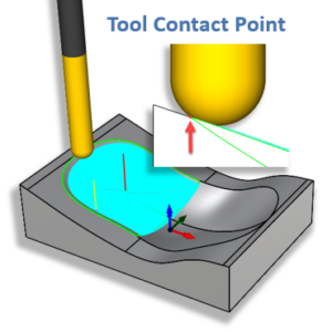
The cause of this waterfall effect is due to the fact that the contact point of the ball cutter with the machining region or the edge of the wall is the same as the tool end when the height of cut level is the same as the height of the edge. As the cut level height decreases, the contact point moves up on the ball of the cutter pushing the tool end outward until finally the side of the tool starts contacting the region. At this point the waterfall effect ends and the cut levels are offset a constant tool radius distance away from the wall.


