 Have you ever used the 3 Axis Horizontal Finishing toolpath and then thought to yourself “I wish it would Clear Flats like 3 Axis Horizontal Roughing does!” Well it can! It’s called Optimized XY Machining and it has its own tab on the Horizontal Finishing dialog. Let’s have a closer look with an excellent example submitted by teacher Tony Cosby of Sisters High School, Sisters OR.
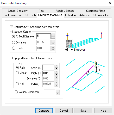
The Optimized Machining tab of the 3 Axis Horizontal Finishing dialog
Optimized machining automatically recognizes these flat areas and inserts projection toolpaths, similar to 3 Axis Projection Pocketing to clean out unmachined areas. This is a highly effective way of maintaining a uniform scallop height on the part. You have Stepover Control of the spacing of these optimized toolpaths as well as Engage/Retract for Optimized Cuts as shown in the dialog above. You can pick the Help button to learn more about each option on the dialog.
Let’s take a closer look at the example shown above:
|  |
The image on the left shows a 3 Axis Horizontal Finishing toolpath without Optimized XY Machining enabled. Notice that in the near horizontal region of the part, the scallop height increases because the Z planes create a wider stepover distance. Now look at the image on the right. Same part, same toolpath but with Optimized XY Machining enabled. Notice that the stepover distance in the flatter areas matches the Z depth distance in the horizontal areas! This allows for the optimum amount of material removal. The entire part and toolpath is shown below in VisualCAD/CAM.

This part example was submitted by teacher Tony Cosby of Sisters High School, Sisters OR. In the main image we see the entire 3 Axis Horizontal Finishing toolpath displayed in VisualCAD/CAM. (Inset Top Right) The flatter areas of the neck leave larger scallop heights. (Inset Bottom Right) With Optimized XY Machining enabled, the step over in the flatter areas matches the Z step down distance in the vertical areas, resulting in a constant scallop height and optimum material removal.

The completed part is shown here. The images of the actual machined part were submitted by teacher Tony Cosby of Sisters High School, Sisters OR.


