• Home
  • Products
    • VisualCAD/CAM
    • RhinoCAM
    • VisualCAM for SOLIDWORKS
    • FreeMILL
    • Compare Products
  • Solutions
    • MILL
    • TURN
    • NEST
    • ART
    • MESH
    • CAD
    • CAD Import
  • Industries
    • Automotive
    • Production
    • Music
    • Woodworking
    • Mold & Die
    • Aerospace
    • Prototyping
    • Jewelry
    • Robotic Milling
    • Education
  • Customer Success
    • Success Videos
    • Case Studies
    • Testimonials
    • Galleries
      • Gallery MILL
      • Gallery TURN
      • Gallery ART
  • Downloads
    • Download Demos
    • Download Posts
  • Sales
    • Product Prices
    • International
    • Schedule On-Line Demos
  • Training
    • Webinars
    • On-Demand Training
    • Classroom Training
    • Self Training
  • Support
    • Request Support
    • Register Products
    • Resources
    • Support Forums
    • Technical Blog
  • Company
    • Blog
    • Partners
      • Companion Products
      • Utility Products
      • CNC Partners
      • 3D Printer Partners
    • Press Releases
    • Newsletters
    • Trades Shows & Events
    • Contact Information
    • Careers
  • Privacy Policy
Call: (949) 654-8163

e-Store Login
  • Facebook
  • Twitter
  • Youtube
  • Linkedin
Milling the Center Cap Logo. Part 2 of 3 (previous entry)
(next entry) The Trinket Box by Bernie Solo. Lid – Part 1 of 2
Previous Article
Next Article
Blog / Milling the Center Cap Tool & Wheel Hub. Part 3 of 3

Milling the Center Cap Tool & Wheel Hub. Part 3 of 3

In the first segment of this post [link to first post] we showed you how Keith Dube of Dubes Custom Street Machines (Hudson, NH) uses VisualCAD/CAM’s TURN module (VisualTURN) to program the toolpaths needed to machine the front and back of the center caps for the wheels on the 811 Car, a 2016 Callaway SC757 Corvette Z06 promotion by 1-Call Concepts and customized by Paul Jr. Designs. In the second segment, we showed you how Keith used VisualCAM’s MILL module (VisualMILL) to complete the center cap machining job.

In this final segment, we see how Keith machines a custom tool to mount/unmount the center caps in addition to thread milling the hubs of the wheel blanks to mount the center caps. Let’s have a look.

Multiple Setups for Indexed (Flipped) Machining

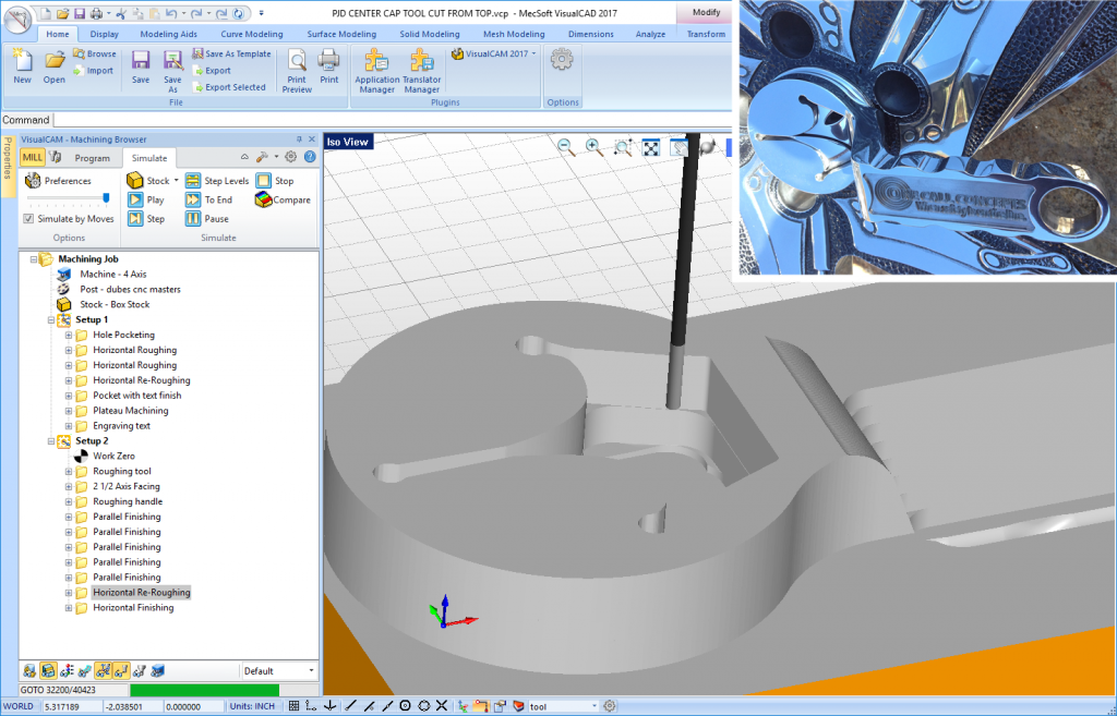
The unique design of this tool requires milling from two sides. Notice Setup 1 and Setup 2 in the Machining Job tree on the left side in the image below. The Professional configuration of VisualMILL allows for unlimited setups within the same part file in addition to a suite of Advanced 3 Axis toolpath strategies.

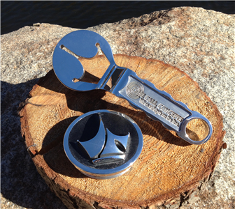
In Setup 1 you see 3 Axis Horizontal Roughing, Re-Roughing and Plateau Machining in addition to 2½ Axis Pocketing, Hole Pocketing and Engraving.  In Setup 2 you see 3 Axis Horizontal Roughing, Re-Roughing, Horizontal Finishing and Parallel Finishing in addition to 2½ Axis Facing.  The completed tool is pictured (inset) after sanding and polishing.

The VisualMILL Professional configuration is shown with multiple setups for the 2-sided machining required on this custom tool part. The cut material simulation for the 3 Axis Horizontal Re-Roughing operation in Setup 2 is shown. (Inset) The completed part is shown after sanding and polishing.

(Left) The center cap tool is shown on the mill prior to the 3 Axis Re-Roughing toolpath being cut. (Right) The completed center cap and tool are fresh off the mill and ready for sanding and polishing.

Thread Milling the Wheels

To mount the center caps on the wheels, Keith used 2½ Axis Profiling and then Thread Milling to machine the access diameter and threads. For Thread Milling you can use a single or multi point thread tool. The Create/Select Tool dialog for Thread Milling tools is shown below.

VisualMILL’s Create/Select Tool dialog is displayed showing the 2½ Axis Thread Mill tool parameters

Here we see how Keith uses multiple 2½ Axis Profiling operations to prep the hub of the wheels for threading. These are listed in the Machining Job tree as O-RING EDGE, RECESS CAP and THREADING OD. Following these, the Thread Milling operation is performed. The operation dialog for Thread Milling is shown in the image below. Notice that the entire wheel geometry does not need to be defined. Being a 2½ Axis toolpath, simple 2D curves can be used.

Here we see the 2½ Axis Thread Milling operation dialog with the Cut Parameters tab selected. Notice the parameters of the selected Thread Mill tool displayed at the bottom of the Machining Objects Browser on the left. Simplified geometry representing the wheel hub is all that is necessary.

(Left) The wheel is mounted on the mill and the 2½ Axis Profiling operations have already been performed and the Thread Mill tool is ready to cut. (Right) The 2½ Axis Thread Mill operation is completed on the mill.

Additional Images

For more information

VisualCAD/CAM, VisualTURN and VisualMILL product and download information and links go here.


Reference Links:

Keith Dube and the awesome projects at Dubes Custom Street Machines

The 811 Car from 1-Call Concepts

The awesome projects from Paul Jr. Designs

The 2016 Callaway SC757 Corvette Z06

Avatar
Don LaCourse

Don LaCourse is an Application Engineer with MecSoft Corporation. Don brings over 20 years of experience in CAD/CAM operations in both automotive and mold design applications. Don also has extensive experience in documenting CAD/CAM products and is actively involved with writing the on-line help as well as creating training tutorials for MecSoft's products.

0 Comments/in Customer Spotlight /
0 replies

Leave a Reply

Want to join the discussion?
Feel free to contribute!

Leave a Reply Cancel reply

Your email address will not be published. Required fields are marked *

Subscribe!

Never miss a post!


Milling the Center Cap Logo. Part 2 of 3 (previous entry)
(next entry) The Trinket Box by Bernie Solo. Lid – Part 1 of 2
Previous Article
Next Article

Follow Us!


The Blog!

MecSoft Blog

Subscribe to MecSoft!


By submitting this form, you are consenting to receive marketing emails from: MecSoft Corporation, 18019 Sky Park Circle, Ste: KL, Irvine, CA, 92614, https://www.mecsoft.com. You can revoke your consent to receive emails at any time by using the SafeUnsubscribe® link, found at the bottom of every email. Emails are serviced by Constant Contact

E-store

e-Store
© Copyright - MecSoft Corporation - CAD/CAM Software
  • Home
  • Products
  • Solutions
  • Industries
  • Customer Success
  • Downloads
  • Sales
  • Training
  • Support
  • Company
  • Privacy Policy