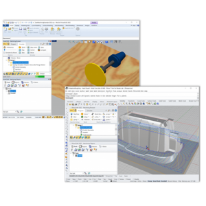
MecSoft’s Advanced 3 Axis Machining methods are well suited for machining complex mold cores and cavities. Mold machining demands accuracy and control throughout the cutting process. MecSoft’s CAM plugins RhinoCAM, VisualCAD/CAM and VisualCAM for SOLIDWORKS provides the accuracy and control needed to machine even the most complex mold cores and cavities. This article takes a look at some of these advanced methods in a real work example.

About the Part
The example part shown here is injection molded using core and cavity plates. This article will look specifically at the mold core plate and explores the application of toolpath strategies included in MecSoft’s Advanced 3 Axis module.
The Machining Job
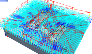
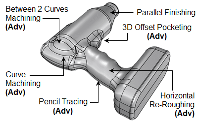
The Machining Job for this mold core block example is shown here on the right. It is a combination of both 3 Axis Methods and Advanced 3 Axis Methods. The (Adv) is annotated to the beginning of each Advanced 3 Axis Method used. You will see that (Adv) Horizontal Re-Roughing, (Adv) 3D Offset Pocketing, (Adv) Between 2 Curves Machining, (Adv) Curve Machining and (Adv) Pencil Tracing are used. The Machining Job shown here is only a subset of all of the toolpaths that would be deployed to complete this job. Each toolpath method is shown in the descriptions below.
The Toolpath Methods
Each toolpath method is illustrated below including their specific characteristics and cutting parameters optimized for 3D mold core machining. Note that the toolpath stepover values are enlarged for clarity. The actual stepover values needed to meet typical mold core surface finish would be much tighter (i,e., Moch small stepover values). Again, these are only a subset of the available Advanced 3 Axis methods available to you. Let’s have a closer look.
3 Axis Horizontal Roughing
Control Geometry: None (default to Part/Stock perimeters), Tool: Flat Mill ½” Dia., Tolerance: 0.04, Stock: 0.01, Cavity/Pocketing Cut Pattern: Offset, Start Point: Inside, Stepover: 15%, Core/Facing Cut Pattern: Island Offsets, Stepover: 25% with Corner Cleanup. Cut Levels: Stepdown: 50%, Cut Level Ordering: Depth First, Clear Flats: Enabled, Engage/Retract: Helical, Adv Cut Parameters: Cut Arc Fitting at Tolerance: 0.02

(Adv) 3 Axis Horizontal Re-Roughing
Control Geometry: 0.5 Offset Closed Curve, Tool: Flat Mill ⅜” Dia., Tolerance: 0.01, Stock: 0.025, Cavity/Pocketing Cut Pattern: Offset, Cut Direction: Mixed, Start Point: Inside, Stepover: 15%, Core/Facing Cut Pattern: Island Offsets, Cut Direction: Mixed, Stepover: 25% with Corner Cleanup. Cut Levels: Stepdown: 0.02, Cut Level Ordering: Depth First, Engage/Retract: Helical, Adv Cut Parameters: Cut Arc Fitting at Tolerance: 0.02
3 Axis Horizontal Finishing
Control Geometry: 0.5 Offset Closed Curve, Tool: 1/16” x 5% Taper Mill, Tolerance 0.0005, Cut Direction: Climb, Tool Action at Containment: Retract to Clearance, Cut Levels: Stepdown: 0.025 Cut Levels Ordering: Depth First, Cut Levels Containment: Top: 1.8, Bottom: 1.5, Entry/Exit: None, Advanced Cut Parameters: Arc Fitting at Tolerance: 0.001


3 Axis Parallel Finishing
Control Geometry: Surface Boundaries, End Condition: On, Tool: 1/16” x 5% Taper Mill, Tolerance: 0.0005, Stock: 0, Cut Control: Cut Direction: Mixed, Start Side: Bottom, Angle of Cuts: 0, Cutting Area Control: Tops Only, Stepover: 0.05, Entry/Exit: Linear, Cut Connections: Straight, Advanced Cut Parameters: Arc Fitting at Tolerance: 0.001
(Adv) 3 Axis 3D Offset Pocketing
Control Geometry: Surface Boundaries, End Condition: On, Tool: 1/16” x 5% Taper Mill, Tolerance: 0.0005, Stock: 0, Cut Control: Cut Direction: Mixed, Pocket Start Point: Inside, Stepover: 0.03, Entry/Exit: Linear, Cut Connections: Straight


(Adv) 3 Axis 3D Offset Pocketing
Control Geometry: Surface Boundaries, End Condition: On, Tool: 1/16” Dia. Ball Mill, Tolerance: 0.0005, Stock: 0, Cut Control: Cut Direction: Mixed, Pocket Start Point: Inside, Stepover: 0.03, Entry/Exit: Linear, Cut Connections: Straight
(Adv) 3 Axis 3D Offset Pocketing
Control Geometry: Surface Boundaries, End Condition: On, Tool: 1/16” Dia. Ball Mill, Tolerance: 0.0005, Stock: 0, Cut Control: Cut Direction: Mixed, Pocket Start Point: Inside, Stepover: 0.03, Entry/Exit: Linear, Cut Connections: Straight


(Adv) 3 Axis 3D Offset Pocketing
Control Geometry: Surface Boundaries, End Condition: On, Tool: 1/16” Dia. Ball Mill, Tolerance: 0.0005, Stock: 0, Cut Control: Cut Direction: Mixed, Pocket Start Point: Inside, Stepover: 0.03, Entry/Exit: Linear, Cut Connections: Straight
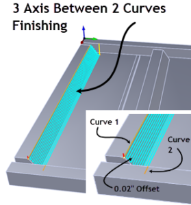
(Adv) 3 Axis Between 2 Curves
Containment: 2 Surface Boundary Curves, Tool: 1/16” Dia. Ball Mill, Tolerance: 0.0005, Stock: 0, Cut Direction: Along, Cut Pattern: ZigZag, Stepover: 0.02, Entry/Exit: Linear, Cut Connections: Straight
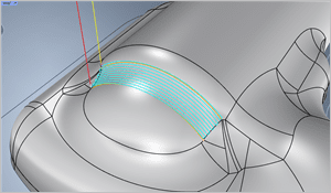

(Adv) 3 Axis Between 2 Curves
Containment: 2 Surface Boundary Curves, Tool: 1/16” Dia. Ball Mill, Tolerance: 0.0005, Stock: 0, Cut Direction: Along, Cut Pattern: ZigZag, Stepover: 0.02, Entry/Exit: Linear, Cut Connections: Straight
(Adv) 3 Axis Curve Machining
Control Geometry: 8 Surface Boundary Regions, Tool: 1/16” Dia. Ball Mill, Tolerance: 0.0005, Stock: 0, Cut Type: Along, Cut Control: ZigZag, Cut Start Side: Right, Cut Both Sides: Yes, Cutting Band Width: 0.05, Stepover: 0.02, Entry/Exit: Linear, Cut Connections: Straight


(Adv) 3 Axis Pencil Tracing
Control Geometry: 0.5 Offset Closed Curve, Tool: 1/16” Dia. Ball Mill, Tolerance: 0.0005, Stock: 0, Cut Direction: Climb, Do Multiple Cuts: No, Entry/Exit: Linear, Cut Connections: Straight
2½ Axis Profiling
Control Geo: 6 Surface Boundary, Tool: 1/4” Dia. Flat Mill, Tol: 0.0005, Stock: 0, Cut Dir: Mixed, Cut Side: Use 3D Model, Loc of Cut Geo: At Bottom, Total Cut Depth: 0.099, Rough Depth/Cut: 0.099 (one pass), Cut Levels Ordering: Depth First, Entry: Lines & Arcs, Tangent, Engage Motion: Radial, Engage Ramp Height: 0.125, Exit: Lines & Arcs, Retract: Radial: 0.25, Retract Ramp Height: 0.125, Departure: Tangent, Adv Cut Parameters, Arc Fit Tol: 0.001


All Advanced 3 Axis Methods
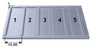
Note: This shows how the perimeter of the advanced 3 Axis toolpath methods project down onto the part surfaces and are contained to the selected surface boundaries.
More about RhinoCAM

RhinoCAM – MILL from MecSoft Corporation is available in five different configurations (Express, Standard, Expert, Professional and Premium). The part shown here was programmed using the Standard configuration. Here are some additional details about each of the available configurations. For the complete features list, visit the RhinoCAM Product Page.
- RhinoCAM MILL Express: This is a general-purpose program tailored for hobbyists, makers and students. Ideal for getting started with CAM programming. Includes 2 & 3 axis machining methods. Includes ART & NEST modules as well!
- RhinoCAM MILL Standard: This configuration includes everything that is in the Express configuration and additional 2-1/2 Axis, 3 Axis & Drilling machining methods. Also now includes 2½ Axis Turning!
- RhinoCAM MILL Expert: Suitable for 4 Axis rotary machining. Includes the Standard configuration, plus 4 Axis machining strategies, advanced cut material simulation and tool holder collision detection.
- RhinoCAM MILL Professional: Ideal for complex 3D machining. Includes the Standard and Expert configuration, plus advanced 3 Axis machining strategies, 5 Axis indexed machining, machine tool simulation, graphical toolpath editing and a host of other features.
- RhinoCAM MILL Premium: Tailored for complex 3D machining with both 3 Axis and full 5 Axis methods. Includes the Standard, Expert and Professional configurations, plus 5 Axis simultaneous machining strategies.
For the complete features list, we invite you to visit the RhinoCAM Product Page: mecsoft.com/rhinocam
Powerful production CAM for Rhino users!
More about MecSoft Corporation
MecSoft Corporation was founded in December of 1997 by a team of programmers from Unigraphics Solutions (now Siemens PLM) with the aim of providing affordable yet powerful CNC software solutions to the manufacturing industry. Our founding and operating principles are based upon the notion that our most important partner is our customer. This allows us to:
- Develop quality products that meet or exceed customer needs and to:
- Deliver them at a price to performance value that is unbeatable in the industry,
- Provide excellent customer service and support.
MecSoft Corporation is based in coastal Orange County, CA, south of Los Angeles.

MecSoft Corporation
Corporate Office Address:
34145 Pacific Coast Highway, #616
Dana Point, CA 92629-2808, USA
Phone: 949-654-8163
Support: 949-654-8163 x2
Sales: 949-654-8163 x201
For all other information call us at 949-654-8163. To contact us using our web form, please click here.


