 Designer Grains Inc. (Watsonville, CA) is an established fine cabinetry and custom manufacturing business successfully operating in Santa Cruz County for over thirty years. Founded by Sean Sinnott in 1989, Designer Grains is known for providing clients with unique designs, excellent craftsmanship and personal attention. Sean’s ability for creative problem-solving has garnered him an industry reputation of being the “Go-to-Guy” for demanding clients.
Sean’s work has included many private estates and luxury residences throughout the greater San Francisco and Monterey Bay Areas. Commercial projects have been installed in numerous locations throughout the United States. His client list includes well-known Silicon Valley CEO’s, famous Wall Street analysts, car dealers, Fortune 500 CEOs, Las Vegas casinos, and real estate billionaire developers!
We recently sat down with Sean Sinnott to discuss his work with RhinoCAM CNC Software and to take a closer look at this cool RhinoCAM project!
The Rhino Part Geometry
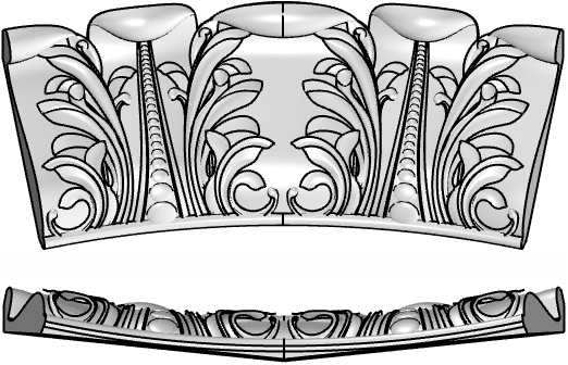
This project will cut one curved Acanthus Crown Molding section, front and back. What is Acanthus? It is a herbaceous plant or shrub native to Mediterranean regions with bold flower spikes and spiny decorative leaves. In architecture, it is used especially as a decoration for Corinthian column capitals. The Rhino part geometry is shown in the illustration below.

The part consists of a solid curved base with “floating” surfaces representing each acanthus leaf. The leaf surfaces are free-floating one upon another giving the pattern both depth and a physical vitality that other flat patterns cannot achieve. Be sure to check out the closeup of this effect in the illustrations below. The stock dimensions are 15” x 14” x 1.75”. In this setup, the Back is machined first and the Front is machine second, One complete set can be machined in the same setup, flipping the stock over and positioned with ¼” alignment pins as needed.

MOpSet Back Side
 RhinoCAM allows you to group operations into what we refer to as MOpSets (i.e., Machine Operation Sets). The MOpSet for the back side is shown here on the right. It includes a total of 3 machining operations, 2½ Engraving, 3 Axis Horizontal Roughing and 3 Axis Parallel Finishing. Each is illustrated below.
2½ Axis Engraving (4 Holes)
To machine the 4 alignment pin holes a 2½ Axis Engraving operation is used with a ¼” diameter flat end mill cutter. Engraving is a very versatile operation that can be used anytime you need the tip of the cutter to follow the containment geometry exactly. In this case the containment geometry is 4 points located on the top face of the stock. Tolerance for this operation is set to 0.001”, cut geometry is located At Top with a Total Cut Depth of 0.5” and Rough Depth/Cut of 0.25”.
Entry and Exit are both set to None and Sorting is set to Minimum Distance Sort. Cut Feed: 75 in/min, Spindle Speed: 7,500 RPM, Estimated Machining Time: 0.9 mins. Below on the left we see the part geometry and the resulting 2½ Axis Engraving toolpath. The resulting cut material simulation is shown on the right.
 |  |
3 Axis Horizontal Roughing
For removing bulk material a 3 Axis Horizontal Roughing operation is used with a ½” diameter flat end mill cutter. The operation is contained to the perimeter boundary curve shown in the part model above. Cut Parameters include an Intol/Outtol of 0.01”, Stock allowance of 0.03” an Offset cut pattern for both Cavity/Pocket and Core/Facing regions, a Mixed cut direction, an Inside start point and a Stepover distance of 0.25”.
The stepdown control is set to 25% of the tool diameter or 0.125” resulting in a total of 7 cut levels. Engage/Retract is set to Path with Angle (A) set to 10 degrees and Height (H) set to 0.05”. Arc Fitting is also enabled with a Fitting tolerance (t) of 0.02”. Cut Feed: 125 in/min, Spindle Speed: 18,500 RPM, Estimated Machining Time: 8.18 mins. Below on the left we see the part geometry and the resulting 3 Axis Horizontal Roughing toolpath. The resulting cut material simulation is shown on the right.
 | |
3 Axis Parallel Finishing
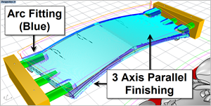
A 3 Axis Parallel Finishing operation is used with a ½” diameter flat end mill. Again the operation is contained to the perimeter boundary curve shown in the part model above. Cut Parameters include an Intol/Outtol of 0.001”, Stock allowance of 0” a Mixed cut direction, Angle of Cuts is 90 degrees and Stepover Control set to a distance of 0.06”.
Entry consists of a Linear Engage motion with both Angle (A) and Length (L) set to zero which eliminates the entry motion and forces the tool to plunge directly above the cut start point. The same is true for the Linear Retract Motion. Again, Arc Fitting is enabled with a Fitting tolerance (t) of 0.002”. Cut Feed: 175 in/min, Spindle Speed: 18,500 RPM, Estimated Machining Time: 6.39 mins. Below on the left we see the part geometry and the resulting 3 Axis Parallel Finishing toolpath. The resulting cut material simulation is shown on the right.
 |  |
Let’s Take a Closer Look
Here is a closer look at each toolpath method illustrated above for the back side.


MOpSet (Front)
 The MOpSet for the Front Side set of operations is shown here on the right. It consists of a total of 3 machining operations, one roughing and two finishing. Each operation is explained and illustrated below.
3 Axis Horizontal Roughing
For removing bulk material a 3 Axis Horizontal Roughing operation is used with a ½” diameter end mill cutter. The operation is contained to the closed perimeter boundary curve shown in the part model above. Cut Parameters include an Intol/Outtol of 0.01”, Stock allowance of 0.03” an Offset cut pattern for both Cavity/Pocket and Core/Facing regions, a Mixed cut direction, an Inside start point and a Stepover distance of 50% (0.25”).
Step Minimization Roughing
This 3 Axis Horizontal Roughing operation includes Step Minimization that allows you to perform a re-roughing operation at the same time. In this case the primary Stepdown Control (dZ) is set to 50% (0.25”). You can then enable the Minimize Stair Steps option that activates an additional field called Intermediate Stepdown % (idZ) that in this case is set 25%. The operation will insert additional cut levels where possible to remove additional stock using the same tool. The step minimization is illustrated in the image below.

Engage/Retract is set to Path with Angle (A) set to 10 degrees and Height (H) set to 0.05”. Arc Fitting is also enabled with a Fitting tolerance (t) of 0.02”. Cut Feed: 125 in/min, Spindle Speed: 18,500 RPM, Estimated Machining Time: 18.88 mins. Below on the left we see the part geometry and the resulting 3 Axis Horizontal Roughing toolpath. The resulting cut material simulation is shown on the right.
 |  |
3 Axis Parallel Finishing
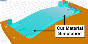
For finishing the front side two 3 Axis Parallel Finishing operations are used. They are identical except for the Stepover Control. The first operation is set to a Stepover of 0.03” and the second is set to a Stepover of 0.01”. This operation uses a ⅛” diameter ball mill cutter. Again the operations are contained to the closed perimeter boundary curve shown in the part model above. Cut Parameters include an Intol/Outtol of 0.001”, Stock allowance of 0” a Mixed cut direction, Angle of Cuts is 90 degrees and Stepover Control set to a distance of 0.03” and 0.01” respectively.
Entry consists of a Linear Engage motion with both Angle (A) and Length (L) set to zero which eliminates the entry motion and forces the tool to plunge directly above the cut start point. The same is true for the Linear Retract Motion. Again, Arc Fitting is enabled with a Fitting tolerance (t) of 0.002”. Cut Feed: 150 in/min, Spindle Speed: 18,500 RPM, Estimated Machining Time for both operations is 49.4 mins. Below on the left we see the part geometry and the resulting 3 Axis Parallel Finishing toolpath. The cut material simulation of the 0.01” stepover path is shown on the right.
 | 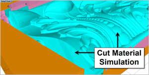 |
The Effect of Floating Organic Acanthus Leaf Surfaces
We mentioned above that the acanthus leaves are modeled using free floating organic NURBs surfaces, one for each leaf. This organic modeling approach can be seen in the closeup image below of the left. The 3 Axis Parallel Finishing cutter path easily follows the part model dropping where needed from leaf to leaf. On the right we see the corresponding cut material simulation.


Let’s Take a Closer Look
Here is a closer look at each toolpath method illustrated above.


The Completed Project
Directly below we see an example of a partially completed part. 3 Axis Roughing is shown on the right while 3 Axis finishing is shown on the left with gold leaf appliqué. Below this we see the actual components installed in the client’s home.

 |  |
| On site completed project showing the curved Acanthus Crown Molding sections installed. | |

More about Designer Grains
Established in 1988, Designer Grains Inc., located in Watsonville, CA consists of professionals that draw upon experience in traditional woodworking, cabinet building, CNC milling, door fabrication, software programming, and complex tool path creation to produce the products provided to their clients. It is this cross-functional team’s experience that enables them to design and build a variety of custom products that are beautiful, functional and long lasting. For more information about Designer Grains, Inc we invite you to visit them online, on Facebook, on Pinterest and Instagram.

See all of the cool projects completed at Designer Grains Inc. with the help of RhinoCAM!
 |  |
| Wine Cellar (Left) and tasting station (Right) | |
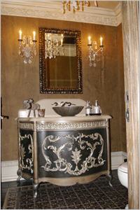 | 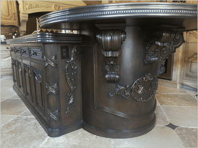 |
| (Left) Curved powder room vanity and (Right) island with curved elements | |
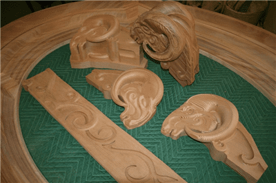 | 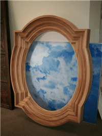 |
| (Left) Misc carved architectural elements (Right) Custom Exterior window casing | |


