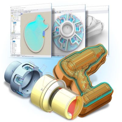
• Home
  • Products
    • VisualCAD/CAM
    • RhinoCAM
    • VisualCAM for SOLIDWORKS
    • FreeMILL
    • Compare Products
  • Solutions
    • MILL
    • TURN
    • NEST
    • ART
    • MESH
    • CAD
    • CAD Import
  • Industries
    • Automotive
    • Production
    • Music
    • Woodworking
    • Mold & Die
    • Aerospace
    • Prototyping
    • Jewelry
    • Robotic Milling
    • Education
  • Customer Success
    • Success Videos
    • Case Studies
    • Testimonials
    • Galleries
      • Gallery MILL
      • Gallery TURN
      • Gallery ART
  • Downloads
    • Download Demos
    • Download Posts
  • Sales
    • Product Prices
    • International
    • Schedule On-Line Demos
  • Training
    • Webinars
    • On-Demand Training
    • Classroom Training
    • Self Training
  • Support
    • Request Support
    • Register Products
    • Resources
    • Support Forums
    • Technical Blog
  • Company
    • Blog
    • Partners
      • Companion Products
      • Utility Products
      • CNC Partners
      • 3D Printer Partners
    • Press Releases
    • Newsletters
    • Trades Shows & Events
    • Contact Information
    • Careers
  • Privacy Policy
Call: (949) 654-8163

e-Store Login
  • Facebook
  • Twitter
  • Youtube
  • Linkedin
How to Detect & Correct Tool Holder Collisions in MecSoft CAM! (previous entry)
(next entry) AlibreCAM Helps Manufacture the Alaskan® Sawmill
Previous Article
Next Article
Blog / Machining Accuracy with AlibreCAM at Granberg International

Machining Accuracy with AlibreCAM at Granberg International

Six years ago Erik Granberg of Granberg International began implementing CNC technology into their manufacturing process and currently has seven (7) Haas CNC machining centers running production full time. Erik has also implemented the Jergan Quick Exchange Die system on each of his Haas machines. This system allows his team to rapidly change setups, minimizing change-over time while increasing production volume and accuracy. Erik designs the many fixture plate configurations in-house using Alibre Design and uses the AlibreCAM plugin to generate the toolpaths and g-code programs needed to manufacture them. 


One of Erik’s custom designed fixture plates for their Quick Exchange Die system is shown with toolpaths displayed for the four ball lock guide pin & bushing hole locations.


The Ball Lock Guide Pin Hole Operation Set

One of the interesting things from a machining perspective are the four outer hole set locations (shown in blue/green) for the fixture plate ball lock guide pins and bushings. In AlibreCAM, only one hole set needs to be programmed. The g-code for the other three can be generated automatically using an XY Instance operation. The Machining Job is shown here.

The critical dimension is the center thru hole diameter of 1.3765” for the press-fit bushing. The g-code for this hole is posted to 6 decimal places of accuracy using a Hole Profiling finishing operation. See Adjusting Toolpath Accuracy below for more information. 

Each hole set consists of two Drill operations, two helical Hole Pocketing roughing operations and a final helical Hole Profiling finishing operation. The first smaller Drill operation provides centering stability for the second larger Drill, which in turn provides the access needed for the two helical Hole Pocketing roughing operations. The second Hole Pocketing roughing operation provides the needed access for the entry and exit of the final Hole Profiling finishing operation which cuts the final hole to the finished diameter. More details for each operation in this set are provided below.

Center Drill
¼” Drill, 0.25” deep, 0.05 peck increment.


Pilot Drill
⅝” Drill, 1.35” deep (thru), 0.25” step increment.


2½ Axis Hole Pocketing
⅜” End Mill, 2.5” dia., 0.26” deep, 40% stepover climb cut, 0.1” stepdown with cleanup pass at each cut level (dark blue). The helical entry is 0.25” dia. x 0.25” deep.


2½ Axis Hole Pocketing (Rough)
⅜” End Mill, 1.300” dia., 0.74” deep, 40% stepover climb cut, 0.15” stepdown with clean up pass at each cut level (dark blue). The helical entry is 0.125” dia x 0.25” deep.


2½ Axis Hole Profiling (Finish) ⅜” End Mill, 1.3765” dia., 0.74” deep x 0.1” helical pitch, climb cut. The linear entry is 0.25” with a 0.25” radius tangent engagement. The retract is also radial at 0.25”with a tangent linear departure of 0.25”


Publishing note: This animated GIF is for web display only. The actual resolution and quality of the cut material simulation that you experience with AlibreCAM is much greater.


Adjusting Toolpath Accuracy

Internally, AlibreCAM tool motions are calculated at double -precision accuracy up to 14 decimal places. The GOTO motion values displayed in the AlibreCAM Toolpath Viewer are shown at 6 decimal places. Here are the adjustments made in Alibre Design and AlibreCAM to tighten the accuracy required for the final finishing Hole Pocketing operation. It should be noted here that accuracy is relative. As you increase accuracy you also increase processing and machining time.

1. Adjust the accuracy settings of the Alibre Design File Properties dialog. For example, set Length Precision and Angle Precision to 6 (Decimal Places).

2. In the AlibreCAM toolpath operation that requires a high degree of accuracy, set the operation Global Tolerance to between 4 and 6 decimal places. The Cut Parameters tab of the Hole Profiling operation dialog is shown below.

3. Before posting your g-code edit your selected post using the built-in AlibreCAM Post Processor Generator. From your Set Post Processor Options dialog select your post from the Current Post Processor list (we selected haas) and then select the Edit… button. This will display the Post Processor Generator for that post.

4. Select the Motion section on the left.

5. For # of Decimal Places, set this to 6.

6. Then also check the box to Show trailing zeros. These selections are shown below.

7. Now, go to the CAM Preferences dialog and from the Machining section, uncheck each of the Arc Output options shown below:

8. Now from the machining Job tree in AlibreCAM, right-click on the operation requiring a high degree of accuracy, and select Post.

9. Here is the sample Haas g-code output for this toolpath in 6 decimal places of accuracy.

More about Granberg International

A special thanks to Erik Granberg and Granberg International for allowing us to share their AlibreCAM success story! For more information about Granberg International and their available product line we invite you to visit them on the web at https://granberg.com/, on Facebook, Twitter, YouTube and Instagram.

Avatar
Don LaCourse

Don LaCourse is an Application Engineer with MecSoft Corporation. Don brings over 20 years of experience in CAD/CAM operations in both automotive and mold design applications. Don also has extensive experience in documenting CAD/CAM products and is actively involved with writing the on-line help as well as creating training tutorials for MecSoft's products.

in Customer Spotlight, Learn CAD/CAM /
How to Detect & Correct Tool Holder Collisions in MecSoft CAM! (previous entry)
(next entry) AlibreCAM Helps Manufacture the Alaskan® Sawmill
Previous Article
Next Article

Follow Us!


The Blog!

MecSoft Blog

Subscribe to MecSoft!


By submitting this form, you are consenting to receive marketing emails from: MecSoft Corporation, 18019 Sky Park Circle, Ste: KL, Irvine, CA, 92614, https://www.mecsoft.com. You can revoke your consent to receive emails at any time by using the SafeUnsubscribe® link, found at the bottom of every email. Emails are serviced by Constant Contact

E-store

e-Store
© Copyright - MecSoft Corporation - CAD/CAM Software
  • Home
  • Products
  • Solutions
  • Industries
  • Customer Success
  • Downloads
  • Sales
  • Training
  • Support
  • Company
  • Privacy Policy