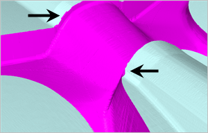
 The #1 priority when machining mold cavity inserts is protecting the parting line! You should never allow the tool tip or tool radius to ride a parting line. This is illustrated in the images below. If this occurs you will see a degradation of the parting line that can cause mismatch and flash in the injection molded parts.
To maintain parting line accuracy and integrity in 3 Axis machining, techniques should be employed that prevent the cutting tool from riding on or along ANY parting line edge. With the use of guide surfaces, the side of the tool always cuts along the parting line in the Z Axis while the tip of the tool aways cuts past the parting line in the X and Y Axis. You can see the difference in quality in the RhinoCAM cut material simulations below!
Guide Surfaces are extra surface geometry that you add to your model that help guide the toolpath around parting line areas. Because they are visible at the time the toolpath is generated, the CAM system takes then into account and treats them like a part surface. In image (B) below we see that a guide surface was added that begins at the parting line and extends vertically tangent to the cavity wall. The height needs only be ½-1 times the diameter of the tool you plan to use to cut the cavity. We extended it higher in our illustrations to help clarify the technique.
We have chosen the 3 Axis Advanced toolpath strategy called 3 Axis 3D Offset Pocketing to cut the cavity. When the tool reaches the top perimeter edge of the parting line, it encounters the guide surface and will continue to cut vertically until it reaches the top of the guide surface. This ensures that the parting line is cut with the side of the tool as it passes it vertically. The guide surface prevents the tool from riding on the parting line.
 |
 |
| NOT RECOMMENDED! 🙁 | RECOMMENDED! 🙂 |
 The tool tip is riding the parting line |
 Only the side of the tool cuts the parting line |
 Simulation results when tooltip rides the parting line |
 Results when the side of tool cuts the parting line |
The two cut material simulations shown above illustrates how the parting line degrades when it is ridden on by the tool, shown in image (C). On the right side image (D) you see the clean and accurate parting line edge created when the tool is guided by the guide surface. Note that the designated guide surfaces must be visible when the toolpath operation that cuts the cavity is executed. In image (B) above, the mold cavity is displayed as grey, the guides surfaces are brown and in image (D) the cut material simulation of the cavity is shown as magenta.
Using Guide Surfaces in XY Tool Motions
Here are some close-up images of the finishing toolpaths at the cavity parting lines.

More Parting Line Comparisons
The following images below further illustrate how the use of guide surfaces can dramatically affect the quality of a 3 Axis mold cavity parting line. The two images are simulations from the same 3 Axis 3D Offset Pocketing Toolpath (not shown). When the toolpath on the left was generated no guide surfaces were displayed. The tool was allowed to ride on and roll over the parting line. When the toolpath on the right was generated, guide surfaces were displayed. The quality and sharpness of the parting line is clearly visible in the simulation.
|
|
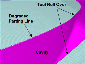 No guide surfaces are used. You see cut traces that the tool left behind when it rolled up along and on the parting line. |
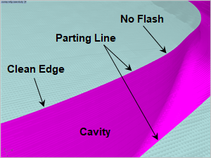 Guide surfaces are used. You see a clean vertical cut resulting in zero mismatch and zero flash encountered on parts coming off this mold in production. |
In the image (C) below we see the XY passes of the tool extend past the parting surface boundary to obtain a clean edge along the top of the parting line. Guide surfaces used for this image are displayed in image (D).
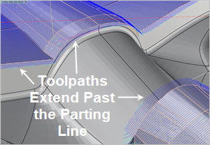 The finishing toolpaths extend past the parting lines in X and Y with the use of Guide Surfaces. |
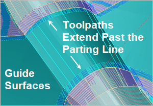 The guide surfaces are displayed. |
 The finishing toolpaths extend vertically past the parting lines in Z with the use of Guide Surfaces. |
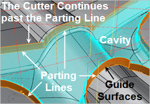 The guide surfaces are displayed. |

Watch the Cut Material Simulation
More about this Part
This mold cavity insert was submitted to us by Al Grifka, CNC Manager at Conley Manufacturing located in Shelby Township just north of Sterling Heights, MI. Al manufactures machined tool & die components for the automotive and aerospace production markets. In addition to mold inserts, companies like Boeing, Cessna, Honda Jet, Ford, GM and Chrysler turn to Conley Manufacturing for specialized jigs, SPC (Statistical Process Control) checking fixtures and CMM (Coordinate Measuring Machine) holding fixtures.
Read more about Conley Manufacturing
 |
|


