 A tool holder collision on a cutting CNC machine can be costly and dangerous! That’s why MecSoft’s CAM plugins provide Tool Holder Collision detection in the Standard (STD) and higher configurations. If you’re a MecSoft CAM user (of VisualCAD/CAM, RhinoCAM, VisualCAM for SOLIDWORKS or AlibreCAM) this blog post will show you how to detect, recognize and correct Tool Holder Collisions before they reach your CNC machine!
Watch the video version of this blog post here!
What is a Tool Holder Collision?
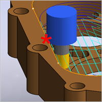
As the name suggests, the tool holder is the tool that holds your actual cutting tool (End Mill, Ball Mill, Face Mill, etc.) to the rotating spindle of your CNC machine. A Tool Holder Collision is when the spindle of your CNC machine attempts any motion that causes the tool holder to come in contact with your workpiece. As you might expect a tool holder collision can cause considerable damage to your CNC machine not to mention bodily harm to the CNC operator! Visual Tool Holder Collision Detection During Cut Material Simulations
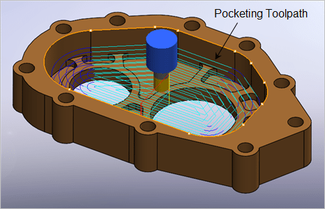
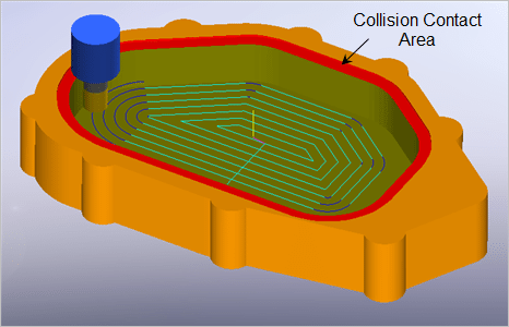
During a cut material simulation, if the tool holder makes ANY contact with the workpiece, the computed area of contact is displayed in red on the simulated stock. This is illustrated in the 2-½ Axis Pocketing toolpath shown in the illustrations below. This feature is part of the Visual Tool Holder Collision capability and is available in Standard (STD) and higher configurations of MecSoft’s PC-based CAM Milling plugins.
 |
 |
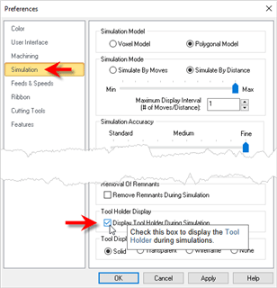
If you do not see the Tool Holder during cut material simulations, make sure that you have it displayed. Check the display toggle at the base of the Machining Browser when the Simulate tab is selected. Also on the CAM Preferences dialog, make sure the checkbox to Display Tool Holder During Simulation is checked. This icon and checkbox are shown below with the Simulate tab on the left and the CAM Preferences dialog on the right.
 |
Visual Tool Holder Collision Detection in the Machining Job Tree
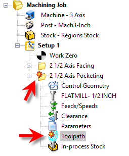
If a Tool Holder Collision occurs, the operation in the Machining Job tree is flagged. If you expand the operation folder you will see that the Toolpath icon is also flagged. An example of these flags are shown below. This feature is part of the Visual Tool Holder Collision capability and is available in Standard (STD) and higher configurations of the product.
If you see ANY of these flags in your Machining Job after a Cut Material Simulation, and are running the Professional (PRO) or Premium (PRE) configuration, go to the section below called How to Compute & Correct Tool Holder Collisions and follow the steps to take corrective action. If you are running the Standard (STD) or Expert (EXP) configuration, edit the Tool Length of the flagged operation and rerun the simulation.
 |
Visual Tool Holder Collision Detection in the Toolpath Viewer/Editor
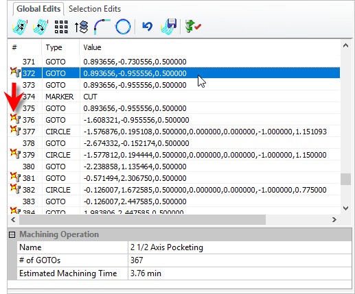
You can gather additional information about a Tool Holder Collision. Just double-left-click on the Toolpath icon in the Machining Job tree. This will display the Toolpath Viewer/Editor. Each motion that has caused a Tool Holder Collision will be flagged. If you left-click on a flagged toolpath motion, the tool will display graphically on the screen at that collision point. Again, this feature is part of the Visual Tool Holder Collision capability and is available in Standard (STD) and higher configurations of the product.
 |
 |
How to perform Analytical Tool Holder Collision Detection and take Corrective Action if Needed
If you see Tool Holder Collisions in your Cut Material Simulations and the operation is flagged in the Machining Job tree, you can follow these steps to take corrective action. This is referred to as Analytical Tool Holder Collision Detection and is available in the Professional (PRO) and Premium (PRE) configurations of the product.
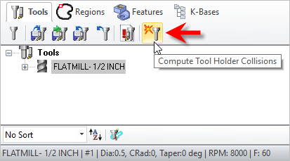
1. Go to the Tools tab on the Machining Objects Browser and select the Computer Tool Holder Collisions icon. It is the last icon on the right, on the Tools tab menu.
 |
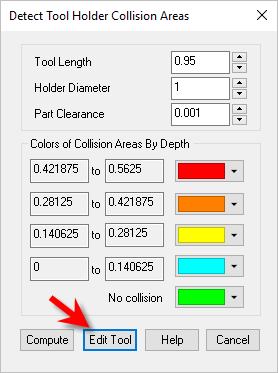
2. From the Detect Tool Holder Collision Areas dialog select the Compute button.
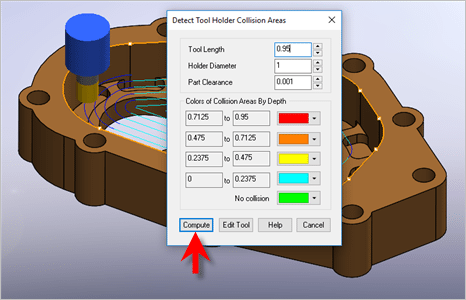 |
3. The toolpath and workpiece are analyzed for tool holder collisions. The results are displayed on the part in a color band of collision areas by depth. If a collision is detected a message displays telling you the Tool Length required to avoid the collision.
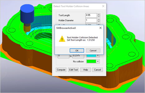 |
4. In this example, we see that the system has detected a Tool Holder Collision and is telling us that we should set the Active Tool Length to a minimum of 1.51250.
5. Pick OK to close the message dialog.
6. Now pick the Edit Tool button from the Detect Tool Holder Collision Areas dialog.
 |
7. This will display the Create/Edit Tool dialog with the Tool used in the flagged operation loaded for editing.
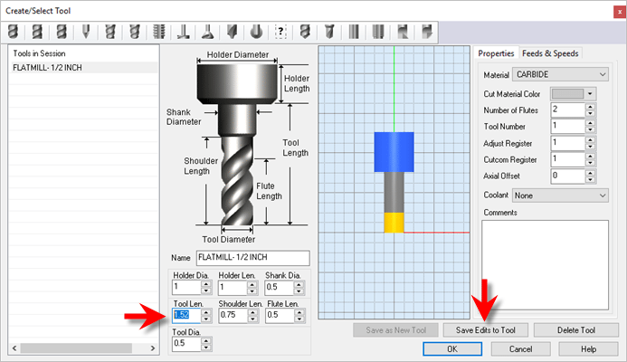 |
8. We set the Tool Length to 1.52, select the Save Edits to Tool button and then pick OK to close the dialog.
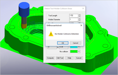 |
10. We see now that the message dialog says No Holder Collisions Detected. A quick check and we also see that the flags on the operation in the Machining Job tree and the Toolpath Viewer/Editor are gone.
Watch the video version of this blog post HERE!
It is demonstrated using VisualCAM for SOLIDWORKS.
Simulation Features by Configuration
The table below lists some of the more advanced simulation features available in MecSoft’s CAM Module plugins and in which configuration they are supported:
| SIMULATION FEATURES | Configuration | ||||
| XPR | STD | EXP | PRO | PRE | |
| Toolpath Animation | |
|
|
|
|
| Cut Material Simulation | |
|
|
|
|
| Advanced Cut Material Simulation | |
|
|
|
|
| Visual Tool Holder Collision Detection | |
|
|
|
|
| Analytical Tool Holder Collision Detection | |
|
|||
| Machine Tool Simulation | |
|
|
||
Let’s Review
Let’s to recap of what we’ve learned:
- A Tool Holder Collision can occur during any toolpath where the total Z depth of the cut motion is greater than the active Tool Length!
- ALWAYS perform a complete cut material simulation on all operations before posting G-Code to your CNC machine!
- In Visual Tool Holder Collision Detection, available in Standard (STD) and higher configurations, collisions are displayed graphically during simulation and are also flagged in your Machining Job and in the Toolpath Viewer/Editor.
- If you have the Professional (PRO) or Premium (PRE) configuration, use the Compute Tool Holder Collision Areas dialog to check for collisions and don’t forget to edit the active tool and then check for collisions again until the system tells you that no collisions are detected!
- Always keep your CNC machine tool and it’s operator safe from Tool Holder Collisions!


