How to Customize Materials Data for Feeds & Speeds Computation

Search

Blog Categories

Note: This blog post is intended for advanced users who are familiar with XML text editing and have administrative access to their Windows Operating System.  MecSoft’s CAM plugins have a built-in Feeds & Speeds Calculator that can suggest Spindle Speeds and Cut Feed Rates based on your stock material and active tool parameters!  However, what if you are cutting stock material that is currently not in our Materials Library?  Or what if you don’t like what is currently assigned for the material of your choice in the Materials Library?  This post will show you how to customize MecSoft CAM to add and manage multiple material files as well to add your own stock materials.  If you are new to MecSoft’s CAM plugins, you can review my earlier post on the Feeds & Speeds Calculator and how it works.

How Materials are Used

First let’s review how material definitions are used in the MecSoft CAM plugins.  From the Stock pane of the Program tab in the Machining Browser you will find the Material icon.  Selecting it will display the Select Stock Material dialog.  Here you can select a stock material from the Material File.  If there is an associated Material Texture file, then this texture is assigned to the stock model and rendered on the graphics window.  This texture rendering on the stock can be toggled on or off using the Material Texture Visibility icon, located at the base of the Machining Browser.

The Material icons in the Machining Browser

The Select Stock Material dialog

Also, from the Feeds & Speeds tab on the Create/Select Tool dialog you can select Load from File to display the Feeds & Speeds Calculator dialog.  The Material selection in this dialog will default to the stock Material you have previously selected from the Select Stock Material dialog (shown above). 

Location of Material Files

The Material selections available to you from these dialogs are retrieved from a Feeds & Speeds XML file installed with the program.  There are separate files for INCH and METRIC units.  The files are located in the Materials folder of the ProgramData install path of the program.  Here is an example: C:ProgramDataMecSoft CorporationVisualCAM 2017Materials.

Maintaining Multiple Material Files

You can create your own Material Files and store them in the default folder.  The CAM system on startup will load all material files in the folder specified in the dialog above as long as the units of the material files match the part units that you are working with.  If the system finds multiple material files with matching units, it will populate the drop-down control in the Materials dialog allowing you to select a specific material file to suit your needs.

Note: You need to make sure that you have the units specified correctly in your customized materials XML files or your material files will not appear in the dialog list.  See item #5 in the Editing the Feeds & Speeds XML File section below for the correct Units format.

Having multiple material files can help manage different materials and associated feeds & speeds data without having to cram all of the data into one file.  In addition, multiple material files may be useful if you have multiple machines in the shop with different power capabilities and you want to use different feeds and speeds settings per machine.  Under this scenario you could have one material file per machine saved in the default folder and load the correct material file depending on which machine you are programming toolpaths for.

Editing the Feeds & Speeds XML File

Material files can be edited to customize the data stored in these files to suit your shop needs.

CAUTION!! – Before editing material files – Make sure you create a copy and keep them in a safe place, outside of the install path of the program.  Also, make sure you maintain the XML format of these files or the Feeds & Speeds Calculator may not work properly.  The file names are:

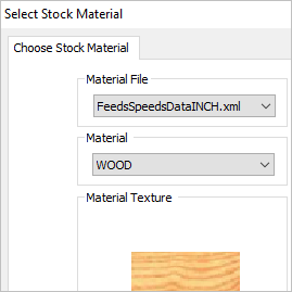
FeedsSpeedsDataINCH.xml FeedsSpeedsDataINCH.xml

Here are the steps required to addnew material definitions.  Be sure to read these steps carefully:

  1. Make a backup copy of the Feeds & Speeds XML files!
  2. Edit the XML file to add the material definitions needed, paying close attention to the format of the XML file.  This file can be edited with any ASCII text editor such as Notepad or any XML editor.
  3. Each Material defined in the XML file has several records (or lines of text) associated with it.  Each line of text defines information about that Material for each instance it is referred to by the Feeds & Speeds Calculator.  Here is a sample section for Aluminum 2024.

<Version>1.0</Version>
<Units>Imperial</Units>
<FeedsSpeeds>
<Material>
<Name>ALUMINUM – 2024</Name>
<TextureFile>ALUMINUM.bmp</TextureFile>
<FeedsSpeedsRecord>MILLING, CARBIDE, 1600.00, 0.0040</FeedsSpeedsRecord>
<FeedsSpeedsRecord>MILLING, HSS, 400.00, 0.0040</FeedsSpeedsRecord>
<FeedsSpeedsRecord>MILLING, CERAMIC, 400.00, 0.0040</FeedsSpeedsRecord>
<FeedsSpeedsRecord>DRILLING, CARBIDE, 960.00, 0.0048</FeedsSpeedsRecord>
<FeedsSpeedsRecord>DRILLING, HSS, 240.00, 0.0048</FeedsSpeedsRecord>
<FeedsSpeedsRecord>DRILLING, CERAMIC, 240.00, 0.0048</FeedsSpeedsRecord>
<FeedsSpeedsRecord>TURNING, CARBIDE, 1800.00, 0.0200</FeedsSpeedsRecord>
<FeedsSpeedsRecord>TURNING, CERAMIC, 1800.00, 0.0200</FeedsSpeedsRecord>
<FeedsSpeedsRecord>TURNING, CERMET, 1800.00, 0.0200</FeedsSpeedsRecord>
</Material>……

Here is what the file looks like in tabulated form:

  1. You will need to know the Surface Speed and Feed/Tooth specifications for each instance of the Material you are adding to the XML file.  Here is the information format:<FeedsSpeedsRecord>MILLING, HSS, 400.00, 0.0040</FeedsSpeedsRecord> Module, Tool Material, Surface Speed, Feed/Tooth
  2. You need to make sure that you have the Units format specified correctly in your custom material XML files.  It is defined on the 2nd line of the Materials XML file.  For Inch units use <Units>Imperial</Units> and for Metric units use <Units>Metric</Units> as shown here for Inch:<Version>1.0</Version> <Units>Imperial</Units> <FeedsSpeeds> <Material>
  3. There is also a bitmap image file (*.bmp) associated with each Material type defined in the XML file.  This image defines the texture that is applied to the Stock material when the Toggle Material Texture Visibility icon is enabled.  The image is also displayed in the Select Stock Material dialog.

Let’s Review:

Adding specific materials you use regularly in your shop to the Feeds & Speeds Calculator in MecSoft’s CAM plug-ins can save toolpath programming time and help ensure cut surface quality and machining time accuracy.  Just be sure to review this post carefully.  A summary is also listed below.  If you need help, you can always contact us at MecSoft Support via the phone, web or email.

  1. You can select a Material to be applied to your Stock definition.
  2. The selection of materials are retrieved from an external data file (example: FeedsSpeedsDataINCH.xml) located in the install path of the MecSoft CAM program on your computer.
  3. The XML data file can be edited with any ASCII text or XML file editor.
  4. The XML data file also contains information about the MecSoft CAM ModuleTool MaterialSurface Speed and Feed/Tooth for each instance of the material.
  5. The stock material selected is used by the Feeds & Speeds Calculator to suggest Surface Speeds and Cut Feed Rates.
  6. The Feeds & Speeds Calculator is displayed when you select Load from File from the Feeds & Speeds tabs of the Create/Select Tool dialog or from each toolpath operation dialog.
  7. You can manually add more materials to the XML data file.  You will need to know the recommended Surface Speed and Feed/Tooth specifications for the material you are adding based on each Tool Material type.
  8. It is very IMPORTANT that you make a backup copy of these XML files if you plan to edit them.  Also, the text format of the XML files is VERY IMPORTANT.  If the format is incorrect, the Feeds & Speeds Calculator may not work properly!  Make sure that the Units format on line 2 matches the Units you plan to use in your part files.
  9. Each material also has a bitmap image texture file (*.bmp) that is located in the same folder.  The material texture image is shown in the Select Stock Material dialog and is also applied as a texture map to your stock when the Toggle Material Texture Visibility icon is enabled.

See Also:

From the blog

The latest industry news, interviews, technologies, and resources.
Don LaCourse

Don LaCourse

Don LaCourse is an Application Engineer with MecSoft Corporation. Don brings over 20 years of experience in CAD/CAM operations in both automotive and mold design applications. Don also has extensive experience in documenting CAD/CAM products and is actively involved with writing the on-line help as well as creating training tutorials for MecSoft's products.

Try us out,

no strings attached!

Download Demo Form

Name(Required)
Product of Interest(Required)
This field is for validation purposes and should be left unchanged.

Name(Required)
Product of Interest(Required)
This field is for validation purposes and should be left unchanged.