Hole Machining in 2 & 3 Axis CAM Part 2: Cutting Parameters
Blog Categories
Welcome to our 4-Part series on Hole Machining in 2 & 3 Axis CAM using MecSoft’s CAM plug-ins. The complete 4-part Guide is available to all AMS subscribers as part of your CAMJam Self-Training package. See How to Download your CAMJam Training Materials for information about CAMJam and how to reap the benefits of your AMS subscription!In part 2 of our series we explore the Hole Cutting Parameters available to each hole operation. You will learn about each hole type’s canned cycle code properties and the Cut Parameters of two 2 Axis Milling toolpath strategies that are used exclusively for cutting holes. These are 2 Axis Hole Pocketing and 2 Axis Hole Profiling. Hole Sorting Rules are also included in this section.The following 4 blog articles are included in this series:
Each hole operation dialog has a Cut Parameters tab that contains all of the cycle parameters needed to define the hole. For example the Drill operation dialog includes a Drill Type selection menu that allows you to define the type of drill cycle to define. For drilling, the menu includes Standard Drill, Deep Drill, Break Chip Drill, Countersink Drill as well as four User Defined Drill Cycles. The Canned Cycle Parameters and the Hole Milling parameters are discussed in a separate section below.
Standard Drill
Deep & Peck Drill
Countersink Drill
Tap
Bore
Reverse Bore
The tables below list the canned cycle parameters supported by each hole type. You will notice that some parameters enable or disable other parameters. For example, in the CountersinkDrill type, CountersinkDiameter is enabled and Depth is disabled.
Example G-Codes:
G77X1.2374Y1.2374Z-0.5R0.1F14.667
Tap Cycle Cut Parameters
Parameter
Reverse Bore G77
User Defined Reverse Bore
Depth
Location At Top
Location At Bottom
Location Pick Top
Projects to 3D Model
Dwell Off
Dwell Time/sec
Dwell Rev/rpm
Approach Distance (R)
Tool Orientation
Hole Milling Operations
For larger holes you can select from one of the 2 Axis Milling toolpath strategies that are specifically designed for cutting circular holes and pockets using mill cutting tools. These include 2 Axis Hole Pocketing, 2 Axis Hole Profiling. It should be noted here that these are not canned holes cycles. They are 2 Axis mill cutting paths that output Linear, Arc and Helix motions. Hole Pocketing combines a helical entry motion with a spiral cut motion at each cut level. Hole Profiling is a helical cut motion combined with entry and exit motion.
Hole Pocketing Example
Hole Profiling Example
Hole Milling Cut Parameters
In addition to the Location of Cut Geometry parameters, additional Cut Parameters include a global Tolerance (t), Hole Depth (H), Hole Diameter (D), Cut Direction and Helical Pitch. Hole Pocketing also includes Stepdown (Dz), Stepover (S) and the ability to add a Cleanup Pass at each cut level. Both of these operations allow you to optionally create full 360 degree helical motions and output each helix individually in the posted G-Code. The cut parameters for each operation type are listed below.
Hole Pocketing Cut Parameters
Hole Pocketing Cut Parameters
Hole Pocketing/Profiling Cut Parameters
Parameter
Hole Pocketing
Hole Profiling
Tolerance (t)
Location At Top
Location At Bottom
Location Pick Top
Hole Depth (H)
Depth from 3D Model
Hole Diameter (D)
Use Arc Diameter
Cut Direction
Stepdown (Dz)
Stepover (S)
–
Do Cleanup Pass
–
Helical Entry
–
Linear Entry
–
Radial Entry
–
Ramp Entry
–
Full 360 Degree Helix
–
Output each Helix Individually
–
Hole Sorting Rules
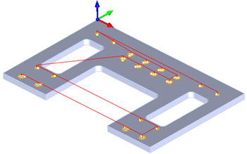
If you have many holes to machine in one operation, you can take advantage of the Sorting tab on each hole operation dialog. It allows you to perform a Minimum Distance Sort and Directional Sort of the holes. In Minimum Distance Sort you can specify the starting location such as Lower Left, Upper Right, etc. The program will calculate the hole machining sequence based on the distance between holes.
If you have a lot of holes in a close pattern this option will keep the machining time to a minimum. If you have a lot of holes in multiple patterns you can use the Direction Sort option. This allows you to specify a Primary and Secondary Direction as well as the Traversal Pattern (i.e., Zig or ZigZag). The Sort tab is also available all Hole operation dialogs as well as many other Milling operations.
Hole Sorting Rules tab (No Sort Selected)No Sorting Selection from Sorting TabHole Sorting Rules tab (Minimum Distance Selected)Minimum Distance / Upper Left Selected from the Sorting TabHole Sorting Rules tab (Direction Selected)Directional Sort, High to Low, ZigZag Selected from the Sorting Tab
MK Fabrication, a sister company of General Fence, Inc., is a growing full service fabrication shop with mobile capability. Built on quality and customer service,
MK Fabrication, a sister company of General Fence, Inc., is a growing full service fabrication shop with mobile capability. Built on quality and customer service,
With the release of RhinoCAM 2024 and VisualCAD/CAM 2024, new functionality and changes are being introduced. We have improved the quality of our product with
MecSoft Releases RhinoCAM 2024 and VisualCAD/CAM 2024 Dana Point, CA, Feb 26, 2024: MecSoft Corporation, the developer of industry-leading CAM software solutions, has announced the
Don LaCourse is an Application Engineer with MecSoft Corporation. Don brings over 20 years of experience in CAD/CAM operations in both automotive and mold design applications. Don also has extensive experience in documenting CAD/CAM products and is actively involved with writing the on-line help as well as creating training tutorials for MecSoft's products.
 Welcome to our 4-Part series on Hole Machining in 2 & 3 Axis CAM using MecSoft’s CAM plug-ins. The complete 4-part Guide is available to all AMS subscribers as part of your CAMJam Self-Training package. See How to Download your CAMJam Training Materials for information about CAMJam and how to reap the benefits of your AMS subscription!
In part 2 of our series we explore the Hole Cutting Parameters available to each hole operation. You will learn about each hole type’s canned cycle code properties and the Cut Parameters of two 2 Axis Milling toolpath strategies that are used exclusively for cutting holes. These are 2 Axis Hole Pocketing and 2 Axis Hole Profiling. Hole Sorting Rules are also included in this section.
The following 4 blog articles are included in this series:
Welcome to our 4-Part series on Hole Machining in 2 & 3 Axis CAM using MecSoft’s CAM plug-ins. The complete 4-part Guide is available to all AMS subscribers as part of your CAMJam Self-Training package. See How to Download your CAMJam Training Materials for information about CAMJam and how to reap the benefits of your AMS subscription!
In part 2 of our series we explore the Hole Cutting Parameters available to each hole operation. You will learn about each hole type’s canned cycle code properties and the Cut Parameters of two 2 Axis Milling toolpath strategies that are used exclusively for cutting holes. These are 2 Axis Hole Pocketing and 2 Axis Hole Profiling. Hole Sorting Rules are also included in this section.
The following 4 blog articles are included in this series: