Feed Rate is one of the most important factors to consider when implementing any CNC strategy. Simply put, feed rate is the speed at which the cutter engages the part and is typically measured in units/minute. Suggested cut feed rates will vary depending on the type of material you are cutting (i.e., aluminum, steel, wood, acrylic, etc.), the material of the cutter (carbide, high speed steel, ceramic, etc.) and many other cutting factors including desired surface and the characteristics of the CNC machine itself.
Why is Cut Feed Rate Important?
Feed Rate is important because it is directly related to virtually every aspect of NC machining from safety and productivity, to tool life, surface finish and part quality. It can also contribute to wear on on the CNC machine’s mechanical components. CNC machines, employ servo motors to electromechanically control the linear motion of the cutter in each principal axis (X, Y & Z).
Consider this. The cutter is engaged in the material and accelerating at 100 inches/minute along a linear path. When it comes to a change in direction such as a corner, it must decelerate to a dead stop precisely at the corner point, change directions, and then accelerate to 100 inches/minute to continue cutting. This rapid deceleration results in increased torque loads on the CNC machine.

Figure 1: The principal axes of a 3 Axis CNC machine. Image courtesy of AirMotive Specialties, Inc. & ShopSabre.
Feed Rate Exemplified
The example below illustrates the feed rate for a 2½ Axis Profiling operation on a 2-inch square rectangle consisting of four linear cuts, each cut being 2 inches long. For practical purposes, we use a cut feed rate of 100 in/min. The tool cutter is shown at its approach position. As it begins cutting, the tool quickly accelerates to 100 in/min. When it reaches the first 90-degree corner it decelerates to zero, changes direction and then quickly accelerates to 100 in/min once again.
The posted g-code of the toolpath for the ShopSabre (WinCNC) controller is shown to the right of the illustration below. Notice that on line N8, the tool plunges at 50 in/min (F50.) to the cut start point and then on line N9 accelerates to 100 in/min to begin cutting (F100.). Also, notice that on lines N10 thru N13 the feed rate remains at 100 in/min around each 90-degree corner.
With the cut feed rate for the toolpath set to 100 in/min, what you do not see is in the g-code is that the cutter must stop at each corner shown in the illustration as “0” points, to change direction. The CNC machine controller handles this.
To use a car/driver analogy, just think of yourself as the cutter and you’re driving your car at 100/mph “head-on” to a 90-degree left turn! It would pay to slow down before you hit the turn, right? That is where feed rate optimization comes in.
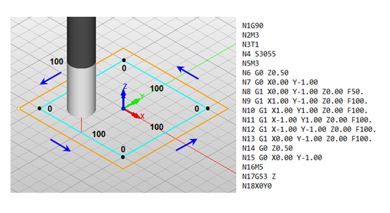
Figure 2: (Left) Cut Feed Rate example for a 2½ Axis Profiling operation on a 2-inch square. (Right) The posted g-code of the example toolpath for the ShopSabre (WinCNC) controller.
Feed Rate Optimization
Each of MecSoft’s 2017 CAM products includes a Feed Rate Optimization feature (Professional & Premium configurations) that addresses head-on the issue of cut feed rate at corners. After generating the toolpath, select it and go to the Toolpath Editor. You will see a new icon on the toolbar called Feedrate Optimization (shown below).

Figure 3: The Feedrate Optimization icon in all 2017 CAM products (Professional & Premium configurations).
This displays a Feedrate Optimization dialog, allowing you to set feed rate reduction parameters. The illustration below shows how setting these parameters can affect a 2½ Axis Profiling operation on a 2-inch square rectangle consisting of four linear cuts, each cut being 2 inches long. We set the Limiting Corner Angle to 90-degrees. We have the Distance before the corner to start reduction and the Distance after corner to reset federate both set to 0.5. We also have the Feedrate reduction percentage set to 0.5
What will these settings do?
Again, notice that on line N8, the tool plunges at 50 in/min (F50.) to the cut start point and then on line N9 accelerates to 100 in/min to begin cutting (F100.). However, at 0.5 inches prior to the first 90-degree corner (see line N10), the cut feed rate drops to 50 in/min. At this reduced speed the tool continues on to the corner, changes direction and proceeds at 50 in/min until it reaches 0.5 inches past the corner point (see line N11) and then returns to the set cut feed rate of 100 in/min (see line N12) until it approaches the next corner.

Figure 4: (Left-Top) Cut Feed Rate example for a 2½ Axis Profiling operation on a 2-inch square with Feed Rate Optimization applied. (Left-Bottom) The Feedrate Optimization dialog (Professional & Premium configurations). (Right) The posted g-code of the example toolpath for the ShopSabre (WinCNC) controller.
Why is Feed Rate Optimization Important?
Well, to use the car & driver analogy – you really might want to apply the brakes before you reach that 90-degree left turn traveling “head-on” at 100 mph!
Using Feed Rate Optimization may not save your life, it will help extend the life of your tools and your CNC machine!
Using Feed Rate Optimization may not save your life, it will help extend the life of your tools and your CNC machine!


