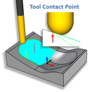
Cutter Compensation, also referred to as Cutter Comp or Cutcom, is used extensively in production (high volume) machining where the machine operator can compensate for tool wear before having to stop and replace the cutting tool or insert. This allows the operator to “dial in” the machining accuracy after a first piece inspection and at regular intervals during a production run.
Watch the Video!
https://youtu.be/lRSbA_ITcyw
Watch the Video!
https://youtu.be/lRSbA_ITcyw
Cutter Comp in MecSoft CAM
In MecSoft’s CAM plugins you can enable cutter compensation when defining the Cut Parameters of the tool path operation. Typically cutter compensation is used in 2½ Axis Profiling and 2½ Axis Pocketing operations. Also, cutter compensation is only enabled during the finishing or clean-up pass of an operation. Cutter compensation is enabled in your posted g-code file using the G40, G41, and G42 codes. Here is a good blog post that explains cutter compensation in more detail.
Note:
Enabling Cutter Compensation DOES NOT alter the cutting coordinates of your posted tool path operation! Enabling Cutter Compensation will ensure the required G40, G41, G42 G-Codes are included in the appropriate locations in the posted G-Code file so that they can be read by your CNC controller.
Steps to Enable Cutter Comp
In MecSoft’s CAM plugins there are a number of steps you need to perform to enable cutter Comp in your posted g-code. These steps are generalized below.
Step 1: The Tool Path Operation Dialog
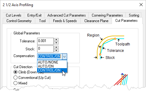
In the Tool Path Operation dialog in MecSoft CAM (i.e., RhinoCAM, VisualCAD/CAM, or VisualCAM for SolidWorks) navigate to the Cut Parameters tab and you will find the Compensation parameter. It is located at the top just below the Tolerance and Stock parameters. Set Compensation to either AUTO/ON or CONTROL/ON. The dialog for the 2½ Axis Profiling tool path is shown below.
Step 2: The Entry Motions Must be Linear
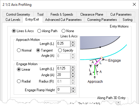
Cutter Compensation will only be enabled when the Entry Motion of your tool path is set to Linear. On the Entry/Exit tab there are controls for defining both the Entry and the Exit motions of the toolpath. You must select Lines & Arcs as the entry method. You can set the Approach Motion Length (L) if you wish. Doing so will satisfy the Linear entry requirement. If you set Length (L) to zero then you must set the Engage Motion to Linear and enter a value for Length (L) there. This will satisfy the Linear entry requirement. The Entry/Exit tab of the dialog is shown below.
Step 3: Set the Cutting Tool Cutcom Register Value
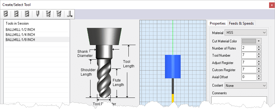
For most CNC controllers, the Cutcom Register value should be set to the same value as the Cutting Tool number. So if you are using Tool #1 the Cutcom Register value would be set to 1. Check with your CNC machine tool manufacturer or supplier to understand how Cutter Compensation is enabled in your controller. The Cutcom Register parameter is located in the Properties tab located on the right side of the Create/Select Tool dialog. An example is shown below.
Step 4: Setup Cutter Compensation in Your Post
MecSoft CAM ships with over 500 post-processors. Most of them will have Cutter Compensation enabled. You need to edit your post-processor to verify that Cutter Compensation is set enabled. In MecSoft CAM, go to the Program tab of the Machining Browser and select Post to display the Select Post-Processor dialog.
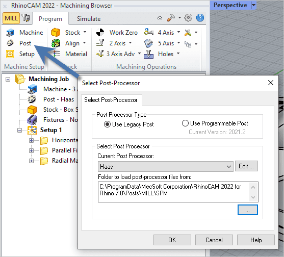
From the dialog, make sure you have your desired post-processor selected from the list located under Current Post Processor. Now select the Edit button located to the right of the name of your selected post-processor. This will display the Post-Processor Generator (PPG).

With the Cutter Compensation from the left selected, you see three macros, one for Cutcom Left, Cutcom Right, and Cutcom Off. These must be defined in order for Cutcom to be enabled in your posted g-code file.
The Posted G-Code
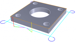
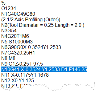
With the above 4 steps completed correctly, Cutter Compensation will be enabled when you post your G-Code file. In the illustration and sample G-Code file below we see Cutcom is first disabled on line N1G40. This is in case Cutcom has been previously left enabled. Then on line N10G41 Cutcom is enabled prior to the linear entry motion.
Add Your Heading Text Here
Lorem ipsum dolor sit amet, consectetur adipiscing elit. Ut elit tellus, luctus nec ullamcorper mattis, pulvinar dapibus leo.


Add Your Heading Text Here
Lorem ipsum dolor sit amet, consectetur adipiscing elit. Ut elit tellus, luctus nec ullamcorper mattis, pulvinar dapibus leo.


