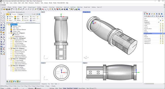
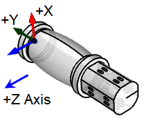
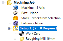
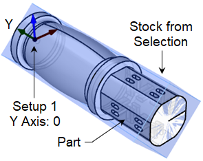
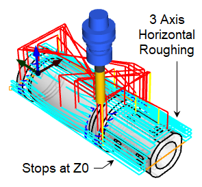
( Y = 0 Degrees )

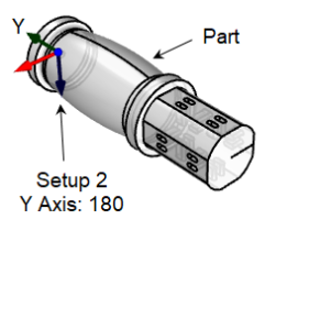
( Y = 180 Degrees )
( Y = 0 Degrees )
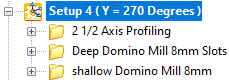
( Y = 270 Degrees )
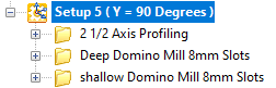
( Y = 90 Degrees )


MK Fabrication, a sister company of General Fence, Inc., is a growing full service fabrication shop with mobile capability. Built on quality and customer service,

MK Fabrication, a sister company of General Fence, Inc., is a growing full service fabrication shop with mobile capability. Built on quality and customer service,

With the release of RhinoCAM 2024 and VisualCAD/CAM 2024, new functionality and changes are being introduced. We have improved the quality of our product with

MecSoft Releases RhinoCAM 2024 and VisualCAD/CAM 2024 Dana Point, CA, Feb 26, 2024: MecSoft Corporation, the developer of industry-leading CAM software solutions, has announced the

Try us out,
No strings attached!