Cool 2-Sided Machining Job from Michel Bélair Luthier

Search

Blog Categories

The RhinoCAM Part

The RhinoCAM part chosen for this case study is shown below. What is interesting about this part? Well, for one thing, it requires machining from both the top and the bottom. Also, there are sharp edges on both the outside and inside that will require some special handling. We will be programming this with 3-axis machining operations. We will be covering RhinoCAM strategies including cut parameters, containment strategies, and fixturing techniques!
The part to machine is a circular ring of medium-density foam.
It measures approximately 106 mm in diameter and 25 mm high.

Reference Surfaces

The part is turned upside down showing the bottom side. The two reference surfaces are shown in magenta.

There are times when additional reference surfaces are added to the RhinoCAM part geometry to help guide the cutting tool in certain areas. For this part we want to do two things: 1) we want to control the depth of the finishing operations on the inner diameter, which allows us to control the toolpath at two different depths, one for the inner diameter and one for the outer diameter. 2) We also want to control the cutting tool as it machines the sharp arc corners on the inner and outer diameters. These edges are indicated at the red dots in this illustration.

Have a look at the part below. It is turned over so the bottom is upward. The two reference surfaces are magenta in color. We do not want the tool to “roll” over the inner edge causing degradation of the edge. The reference surface will guide the tool past the edge. This type of reference surface is used frequently in mold machining to protect parting lines. We are using it here for a similar purpose.

The second is a planar circular surface located on the inner diameter. Since the inner diameter of the part is 82.00 mm (see drawing above), the diameter of the reference surface should be no less than 75.65 mm so that it stops the 6.35 mm diameter finishing ball mill. The Z depth of this reference surface must be at least 3.175 mm below the quadrant of the inner arc. In the illustration below the quadrant, the point is shown with a blue dot.

This is so the full diameter of the cutting tool will proceed to a depth that passes the quadrant point but not all the way through the part. This planar surface is shown as a line in the elevation view below. The arrow indicates the depth to cut on the inner diameter. Similar reference surfaces are used when machining the top side. More on that so keep reading.

Note:

The Rhino layer containing the reference surfaces must be turned ON (visible) when the toolpaths are generated. Once the toolpaths are generated the layer can be turned OFF.

Here is an elevation view of the part oriented for machining the bottom side. The red dots indicate where critical edges are located. The blue dot represents the location of the inner quadrant position. The magenta straight line is the location of the circular planar reference surface. The black arrow shows the depth of the machining on the inner side.

The RhinoCAM Setups

We mentioned that this will be a 2-sided machining job – also referred to as flip-machining. The bottom side will be machined first and does not require any special fixturing. It can be held down using the CNC router’s vacuum table. Then the part will be flipped over and set onto a fixture to machine the top side. The parting plane on the inner diameter is located at the quadrant of the inner arc profile. The parting plane on the outer diameter is located at the bottom edge of the outer arc profile. You can refer to the illustration below.
The parting plane on the inner diameter is located at the quadrant of the inner arc profile. The parting plane on the outer diameter is located at the bottom edge of the outer arc profile.

Setup 1 (Part Bottom – Circular Stock)

This is the first setup in the machining job. Referred to as Setup 1 (Part Bottom – Circular Stock). It will include two 2½ axis Facing operations, a 3 axis Horizontal Roughing operation, and two 3 axis Horizontal Finishing operations. It will employ the use of our two reference surfaces (shown above in magenta). The Machining Job for the setup is shown below.
Here are the toolpaths for the bottom side. The last image in the set below is the cut material simulation and shows how the stock will look after the setup has completed machining.
The first 2½ Axis Facing operation machines the bottom of the part.
The second 2½ Axis Facing operation machines the bottom step.
The 3 Axis Horizontal Roughing operation will clear the material from the inner diameter of the part leaving 1 millimeter of stock around the side walls and clearing the material down to the planar reference surface.
The first 3 Axis Horizontal Finishing operation is used as a pre-finishing operation and clears additional material around the inner side walls again leaving 1 millimeter of stock.
The second 3 Axis Horizontal Finishing operation is the final finishing pass around the inner perimeter. Notice how the toolpath is guided upward past the inner edge and onto the reference surface.
Here we see the completed cut material simulation of Setup 1 (Part Bottom – Circular Stock). Notice the clean sharp edge where the tool was guided past the edge and onto the reference surface!

The Fixture

We mentioned that after the bottom side is machined, the in-process stock is flipped over and then set onto a fixture shown below. The circular array of 24, 3 mm diameter holes shown on the top side of the fixture is where the in-process stock will be set. On the bottom side, we see that there is a circular pocket. This bottom chamber will allow the in-process stock to be held in place utilizing the CNC machine’s vacuum table. Optionally there are mounting holes at each corner that can be used.
Note:
The RhinoCAM Professional configuration allows multiple setups to reside in the same part file. This allows you to design and CAM program both sides of the fixture at the same time as CAM programming the two-sided part!
These images show the fixture that will hold the in-process stock while the top side of the part is machined. Notice the circular array of 3 mm diameter holes and the pocket chamber on the bottom. These will assist with keeping the workpiece down during machining.

Flipping & Fixturing the In-Process Stock

In the images below you see the part and fixture as they look before and after Setup 2 is programmed and machined. Similar to the bottom, the top side also has two reference surfaces (shown in the color green). The first is a flat planar surface placed inside the part to contain the operations to a fixed Z depth (on the inside only).

The second reference surface is actually part of the fixture. You will notice that it is an exact tangential extension of the outer surface of the part. It will serve to guide the finishing pass downward and past the bottom outer edge. This surface will keep the finishing tool from riding on this edge and degrading it.

Here is how the in-process stock looks after Setup 1. It is flipped over and placed onto the fixture shown below left.
Here we see the in-process circular stock mounted on the top of the fixture. On the left, we see the circular stock. On the right, we see the finished part as well as the reference surfaces in green.

This illustration shows a cross-section of the part and fixture. The bottom vacuum chamber and the 3 mm diameter holes are clearly shown. You can also see that the bottom edge of the part’s outer diameter (see the red dot in the illustration) mates with the fixture to form a continuous transition as the cutting tool moves past this outer edge.

You will also see that the bottom-most diameter of the part fits snugly onto the mating pocket in the fixture. In the Rhino CAD geometry, these two diameters are the same dimension. When cutting the fixture, the exact fitting diameter of the pocket can be controlled using the XY Stock allowance parameter in the 2½ Axis Pocketing operation dialog. For example, a negative Stock allowance of -0.005 will overcut the pocket by 0.005. This can be adjusted to achieve the fit required.

Setup 2 (Part Top)

This is the second setup in the machining job. It will include three 3 Axis machining operations. The first is a 3 Axis Horizontal Roughing operation to remove additional unused stock. Next, there is a 3 Axis Horizontal Finishing operation. This is used as a pre-finishing operation with the Stock allowance set to 1 mm. The final toolpath is another 3 Axis Horizontal Finishing operation with Stock allowance set to zero and the cut level stepdown set to 0.25 mm. Setup 2 also employs reference surfaces shown in green. The Machining Job for Setup 2 (Part Top) is shown below.
Here are the toolpaths for the top side. The last image in the set is the cut material simulation and shows how the stock will look after the setup is completed machining. Pay special attention to the bottom outer edge.

(LEFT) On the left, we see the fixture shown without the in-process stock. (RIGHT) On the right, we see the
fixture shown with the in-process stock flipped over and mounted on the fixture.

(LEFT) The first operation is 3 Axis Horizontal Roughing. It will remove additional in-process stock. (RIGHT)
On the right, we see the cut material simulation of the 3-axis Horizontal Roughing operation. Notice that the
excess inner stock has been removed exposing the bottom side finishing operation.

(LEFT) The second operation is 3 Axis Horizontal Finishing. This is a pre-finishing operation that leaves 1
mm of stock on the part. (RIGHT) On the right we see the cut material simulation showing the in-process
stock after the operation is complete. Notice the exposure of the bottom side inner finishing operation.

(LEFT) The third and final operation is another 3 Axis Horizontal Finishing operation. This time the Stock
allowance is set to zero and the cut level stepdown is set to 0.25 mm. (RIGHT) The cut material simulation
shows how the completed part will look before removing it from the fixture.

Here we see a cross-section view of the fixture. The completed in-process stock is shown still mounted on the fixture.
Here is a view of the in-process stock after the part is removed from the fixture
Here is an elevation view of the final in-process stock simulation with the part removed from the fixture. Look at the part edges where the reference surfaces were used. They are clean and crisp with no degradation.

Cool project Michel!

Thank you for allowing us to showcase your work!

More from Michel Bélair Luthier

Michel’s guitars are made with the best quality wood. Western Red Cedar from Vancouver Island and European Spruce from Switzerland. He also has excellent Engelmann Spruce from western Canada. Michel recommends Indian Rosewood for the back and sides because of its excellent acoustic properties and straight grain for stability. Michel also recommends rosewood from Madagascar. The neck is of South American mahogany and African ebony for the fingerboard.

Have a look at some pics from the shop at Michel Bélair Luthier!

Read the full case study here.
Follow Michel Bélair Guitars Online:

More about RhinoCAM Configurations

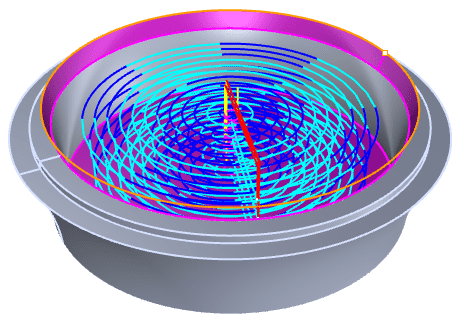
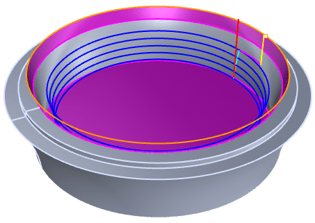
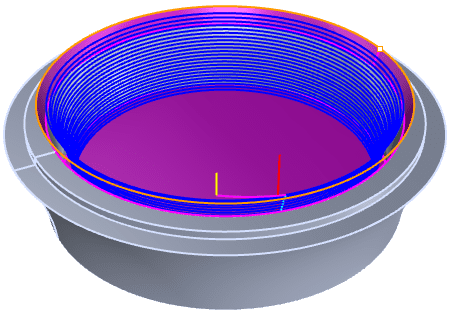
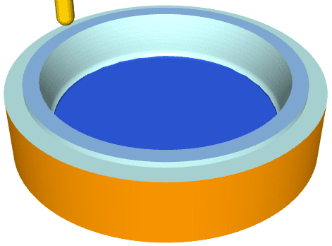
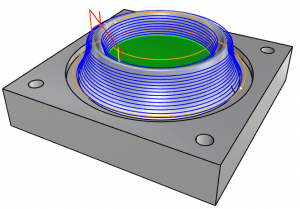
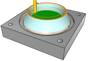
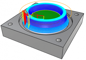
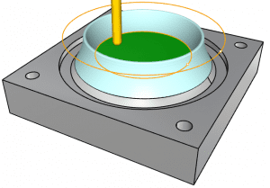
RhinoCAM – MILL is available in 5 different configurations (Express, Standard, Expert, Professional and Premium). The parts shown here were programmed using the Professional configuration. Here are some additional details about each of the available configurations. For the complete features list, visit the RhinoCAM Product Page.

  • RhinoCAM MILL Express: This is a general-purpose program tailored for hobbyists, makers, and students. Ideal for getting started with CAM programming. Includes 2 & 3-axis machining methods. Includes ART & NEST modules as well!
  • RhinoCAM MILL Standard: This configuration includes everything that is in the Express configuration and additional 2-1/2 Axis, 3 Axis & Drilling machining methods.
  • RhinoCAM MILL Expert: Suitable for 4 Axis rotary machining. Includes the Standard configuration plus 4 Axis machining strategies, advanced cut material simulation, and tool holder collision detection.
  • RhinoCAM MILL Professional: Ideal for complex 3D machining. Includes the Standard and Expert configuration plus advanced 3 Axis machining strategies, 5 Axis indexed machining, machine tool simulation, graphical toolpath editing, and a host of other features.
  • RhinoCAM MILL Premium: Tailored for complex 3D machining with both 3 Axis and full 5 Axis methods. Includes the Standard, Expert, and Professional configurations plus 5 Axis simultaneous machining strategies.

For the complete features list, we invite you to visit the RhinoCAM Product Pagemecsoft.com/rhinocam


Powerful production CAM for Rhino users!

From the blog

The latest industry news, interviews, technologies, and resources.
Don LaCourse

Don LaCourse

Don LaCourse is an Application Engineer with MecSoft Corporation. Don brings over 20 years of experience in CAD/CAM operations in both automotive and mold design applications. Don also has extensive experience in documenting CAD/CAM products and is actively involved with writing the on-line help as well as creating training tutorials for MecSoft's products.

Try us out,

no strings attached!

Download Demo Form

Name(Required)
Product of Interest(Required)
This field is for validation purposes and should be left unchanged.

Name(Required)
Product of Interest(Required)
This field is for validation purposes and should be left unchanged.