 2½ Axis machining is the 2nd most common application (behind 3 Axis machining) for all of MecSoft’s CAM plugins. The reason for this is because a large number of parts found in the real world lend themselves to 2½ Axis machining. The majority of 2½ Axis components are simple prismatic shapes composed of drilled holes, flat horizontal faces and straight or drafted verticals walls.
In 2½ Axis machining the cutter moves in a plane in both the X and Y direction while maintaining a fixed Z height. The ½ axis is appended to 2 Axis, to denote the fact that cutting is done in successive fixed Z height planes starting at the highest Z level and stopping at a lowest Z level, thereby machining a complete 3D prismatic part. This method of machining is not quite 3 Axis where all three axes (X,Y and Z) can be continually changed when machining.
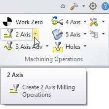
In this post we’ll explore Best Practice methods and understanding for machining components using the following 2½ Axis toolpath strategies in MecSoft CAM:
- Facing
- Pocketing
- Profiling
- Engraving
- Hole Pocketing
- Hole Profiling
If you also machine in 3 Axis or plan to in the future, be sure to check out our blog post Best Practices in 3 Axis Machining!
CAD Geometry & File Formats
Similar to 3 Axis your CAD geometry plays an important role in 2½ Axis machining. Most importantly here, is making the determination that 2½ Axis machining strategies are indeed the best approach. You can only make this determination by reviewing and understanding the part geometry.
At a minimum you need 2D geometry such as lines and arcs (we’ll just call them curves) to machine in 2½ Axis. These curves would lie on a plane parallel to the XY plane and can be at any Z height. However, having an actual 3D model is even better because it allows you to both visualize the part and the machining processes at the same time. In some cases you may want to use a combination of both 2½ Axis and 3 Axis toolpath strategies. In other cases, you can save time by simply using a 3 Axis toolpath strategy.
| If your part contains ANY contours that would require the cutting tool to move simultaneously in all three X, Y and Z axis, you MUST use 3 Axis machining strategies. |
For recommendations on CAD File Formats you can refer to our Best Practices in 3 Axis Machining blog post.
 |
 |

Best Practices
Here are some things to consider regarding CAD Geometry and File Formats specifically for 2½ Axis machining:
- 3D is always better than 2D:
If given a choice always ask for the 3D solid part model. It will remove all ambiguity thereby allowing you to better evaluate the part and your machining job requirements. Native files created from the same CAD system where you are running MecSoft CAM as a plug-in are preferred. If this is not possible, ask for the 3D part in both STEP (*.stp) and IGES (*.igs) file formats. Refer to our Best Practices in 3 Axis Machining blog post for more specific recommendations on CAD Geometry and File Formats. - When curves are better than lines:
If the part has ANY curved edges make sure the CAD file includes actual curve geometry such as arcs, circles, splines, etc. and not just line segments. Avoid SLA and STL file formats if possible. - Think Vector, not Raster:
For 2D geometry, vector drawings (i.e., lines, arcs and curves) are required. You can use DWG and DXF files for this purpose. These are AutoCAD® drawing formats so files from the later versions are better. Raster files are bitmap image files and ARE NOT machinable.
General Machining Checklist
Before you start any toolpath project ask yourself these questions. Knowing the answers before you start can save you time and money down the road.
- Are the Units, Size and Orientation correct?
Check your part file to make sure it is in the expected units (MM or Inches). Check the size of your part. You can do this quickly by selecting the Stock icon from the Machining Job tree. Check to make sure the part is oriented correctly for machining. - Will the part fit on my CNC machine?
If not, can you machine it in sections? Also, can you machine all of the required features from one side or will a secondary setup and machining be required? - Is this a 2½ Axis Part?
If your part has tapered walls then 3 Axis toolpaths may be required. Note that some simple tapered walls can be machined with tapered cutters. So care needs to be taken when evaluating whether a part can be machined purely with 2½ Axis methods. - Can I save time using 3 Axis Toolpaths?
Your part may have many prismatic features that can all be machined using one 3 Axis Horizontal Roughing strategy. With Tolerances set to a finishing value such as 0.001, Stock set to zero and Clear Flats enabled, this 3 Axis toolpath strategy can perform 2½ Axis Facing, Pocketing and Profiling all at the same time. For some parts this is ideal.
Effect of Machining Tolerances
![]() We strongly recommend that you take some time to read our previous post Best Practices in 3 Axis Machining and How to Increase Toolpath Accuracy where we cover the Effect of Machining Tolerances in greater detail. The recommendations we make below apply specifically to your 2½ Axis machining projects.
We strongly recommend that you take some time to read our previous post Best Practices in 3 Axis Machining and How to Increase Toolpath Accuracy where we cover the Effect of Machining Tolerances in greater detail. The recommendations we make below apply specifically to your 2½ Axis machining projects.
Best Practices
Specifically for 2½ Axis machining here are some things to consider:
1. Pay attention to the Global Tolerance:
Machine tools have the ability to follow only two types of curves exactly as defined in ISO 6983, the international standard for numerical control which defines the data format for positioning, linear motions and contouring control systems. These curves are Lines and Arcs (Helixes are included here). Any other type of curve is followed only to the Tolerance accuracy specified in the Global Parameters section of the operation dialog.
Why is this tolerance required?
Because the kinematic joints of a CNC machine tool cannot allow exact conformance to any other type of geometry. So free-form curves as well as other conics such as parabolas, ellipses etc. can only be followed by using a linearized representation of these curves.
2. Use of Arc Fitting:
Facing, Pocketing and Profiling supports Cut Arc Fitting. This is located on the Advanced Cut Parameters tab of the operation dialog. It allows you to fit arcs to consecutive curve segments that lie on the XY plane. The parameter has a Fitting Tolerance (t) value. It defines the maximum deviation of each chord or segment of the original linearized toolpath to the fitted arc.
Arc Fitting Tolerance value recommendation:
This value should be 2 times the toolpath Global Tolerance value for the toolpath to allow enough room for the program to fit 3 consecutive points to an arc motion. So for example, if your resulting toolpath must be within 0.001” of the CAD geometry, set your arc Fitting Tolerance (t) to (0.001) and your toolpath operation Global Tolerance to ½ of that (0.0005”). A value lower than this may not find any linear segments to fit arcs to. A value higher than this may result in arc motions that exceed your tolerance requirements.
The Role of Stock to Leave
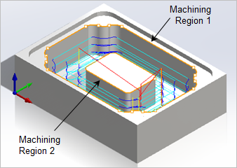
The Stock value in 2½ Axis machining applies to the extents of the cutter paths in the XY plane at each cut level. In the Pocketing operation shown in the illustration below for example, you can clearly see that the Stock value applies to the vertical walls around the perimeter of each pocket. The in-process stock model is shown transparently on top of the part model. The Z depth of the cutter is controlled by the Cut Levels tab of each operation. Refer to the Effective use of Cut Levels & Machining Regions section below for specific recommendations regarding the Z Axis.
 |
 |
In these pocketing operations a positive Stock value of 0.025” was specified.
Best Practices
Here are some best practices regarding stock in 2½ Axis machining:
1. Use of Bridges & Tabs:
Bridges & Tabs are used to prevent the cut piece from falling out or moving as it is being cut. This typically happens when cutting flat sheets of material like paneling. Even if you have a vacuum table to hold down parts, you may want to use Bridges & Tabs to give your stock added stability during machining. The size of the tabs will depend on your stock material. Cutting wood will require larger tabs while tabs for cutting metal can be smaller. Tabs can be positioned automatically or manually. You will need to consider how you plan to remove the excess tabs after machining.

2. Stock applies to the XY Plane:
Remember that the Stock value on the Cut Parameters tab of the toolpath operation dialog refers to the vertical sides of the cutting tool as it moves in the XY plane. It determines how much stock to leave or remove in relation to the machining regions selected for the operation. Use the Cut Levels tab to adjust any stock to leave in the Z axis.
3. Minimize your Stock Size:
Use minimum stock sizes when possible. This will save both material and machining time.
4. Using a Negative Stock Value:
If your CAD geometry does not account for fit, you can use positive and negative stock in conjunction on mating parts to achieve the fit desired during assembly (press fit, slip fit, etc.).
5. For Roughing and Finishing:
2½ Axis operations can be used for both Roughing and Finishing by simply adjusting the amount of Stock to leave. For finishing operations, the stock value is typically set to zero so as to produce the desired part geometry.
Effective Use of Cut Levels & Machining Regions
![]() We mentioned previously that in 2½ Axis machining the cutter moves in the XY Plane while maintaining a fixed Z depth. The Z depth for each XY pass in relation to your selected Machining Regions is controlled using the Cut Levels tab of the operation dialog. An understanding of how cut levels are controlled is essential.
We mentioned previously that in 2½ Axis machining the cutter moves in the XY Plane while maintaining a fixed Z depth. The Z depth for each XY pass in relation to your selected Machining Regions is controlled using the Cut Levels tab of the operation dialog. An understanding of how cut levels are controlled is essential.
We recommend that you review our blog post Understanding Cut Levels in 2½ Axis Machining where we go into this topic in detail.
Best Practices
Here are some best practice methods regarding Cut levels and Machining Regions in 2½ Axis machining:
1. Understand the Location of Cut Geometry:
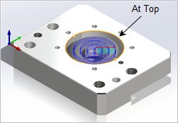
Location of Cut Geometry refers to the machining regions you have selected in the Control Geometry tab for the operation. It is essential that you understand where this geometry is located in relation to the starting Z level of the cut. Ask yourself “Where is my Cut Geometry?” The available options are At Top, At Bottom and Pick Top.
 |
 |
2. Know when to use the Pick Top option:
If you are machining from 2D geometry then you may be in a situation when the Pick Top option is required. In the example shown below there is no 3D model. The Control Geometry is a 2D drawing located on the XY plane at Z0 (zero). You are looking at the resulting stock after the pocket is cut. Notice that the Stock Height and the Pick Top value are the same (0.5). Pick Top allows you to tell the system where to start the Z level cut.
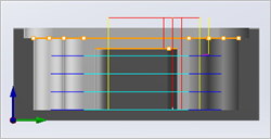
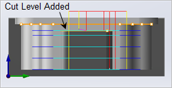
3. Understand your Part Region Heights:
Your machining regions might not all be on the same Z level! This can occur when you have islands within regions that are located at different levels. The example part shown below has an island that is lower than the perimeter of the pocket. The Clear Island Tops option on the Cut Levels tab allows you to add a cut level to clear this area.
 |
|
 |
 |
4. Use Rough & Finish Depths:
You can use the Cut Levels tab to automatically divide your cut levels into a Rough Depth and a Finish Depth, each with their own unique Depth/Cut values.

5. To save time, use 3D Model to Detect Depths:
If your part is a 3D solid or surface model, you can save time by checking the box to Use 3D Model to Detect Depth on the Cut Levels tab. Then just set your Depth/Cut values.
6. Understand how Radiused Mills behave near an edge:
It is important to understand how Z heights AND the XY perimeter of each machining region are honored by radiused cutting tools. We have reduced the cut level in the following example to illustrate the waterfall effect of the Ball Mill tool as it makes contact with the edge of the machining region.

7. The proper use of Avoid Regions:
Avoid Regions are typically used to avoid objects such as clamps and fixtures. When using Avoid Regions make sure they overlap the Machining Regions as shown in the examples below. They can be selected from the Avoid Regions tab on the Control Geometry section of the Facing, Pocketing and Profiling toolpath dialog.
 |
 |
8. Understand Nested Machining Regions:
When regions are nested inside one another, it is important to realize where the cutter will machine. When using a Pocketing toolpath, the system treats any nested region as islands and will cut anything between the outer pocket region and any of its inner nested islands.
On the machining regions shown below, the nested inner regions become islands within the outer pocket region and the cutting area is shown hatched. In addition to this, if another region is nested inside of an island region, as shown below, it will be treated as a pocket region. The system applies the same rule to any depth of nesting. 
9. Optimize your Feed Rates:
There will be instances when you may not want the cutting tool to accelerate at the full Cut Feed value you have assigned for either the tool or the toolpath operation. The table below lists a few of these conditions and how to control them. See our blog post Feed Rates Explained – Extend the Life of Your CNC Tools and Machines for more detailed information on feed rates.
| Conditions | Controls |
| When plunging between Cut levels | Located on the Feed Rate Reduction Factors section of the Feeds & Speed tab for both the tool and the operation |
| During the first XY pass when the full width of the tool is engaged in material | |
| At sharp corners | Select Feedrate Optimization from the Global Edits tab of the Toolpath Editor (Professional & Premium configurations) |
Applying 2½ Axis Toolpath Strategies
In most cases your part geometry will dictate which 2½ Axis toolpath strategy to use. For example, if your part has profiles, pockets, holes, chamfers, etc. Also, most 2½ Axis toolpath strategies can be used as roughing operations by simply specifying an amount of stock to leave. Below we have listed the most common 2½ Axis toolpath strategies and examples of their use. The Best Practices that we have discussed above will apply to ALL of the 2½ Axis toolpath strategies.
Facing
The Facing toolpath strategy is a method of generating planar toolpaths using Machining Regions as the part geometry limits. The toolpath begins at the top Z value and stops at the bottom Z Depth you specify. The outermost region in facing is treated as a region enclosing a “core” part and thus the system assumes it is safe to approach this region from the OUTSIDE. Such scenarios as shown below. Note that the cutter can be positioned outside these selected regions without violating the part geometry. As a consequence, the system positions the center of the cutter ON the outermost region when cutting. The supported cut patterns are Linear or Island Offset. Clean up passes can be added and stock left around islands automatically as shown on the left image below.
 |
 |
Facing is a planar area clearance operation that supports many different cutting tool types. End Mills and Face Mills are most commonly used. Notice that only the selected Machining Regions are considered allowing sub features such as holes and pockets to be ignored. A cleanup pass at islands can be added automatically.
Pocketing
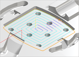
The Pocket toolpath strategy is also a method of generating planar toolpaths using regions as the part geometry limits. The main difference with Pocketing and Facing is that the perimeter of the cutting tool stops at the selected regions. Thus in pocketing the system assumes that you are machining a “cavity” type of part. This means the cutter cannot be positioned outside or on any of these regions. Typical situations where a pocketing toolpath will be suitable are shown below. The toolpath begins at the top Z value and stops at the bottom Z Depth you specify. The supported cut patterns include Offset, Offset Spiral, Linear, Spiral, Radial and High Speed.
 |
 |
In Pocketing, the diameter of the cutting tool stops at the selected regions. In the example on the left the Offset cut pattern is used. On the right we see the characteristic tangential loops of the High Speed cut pattern.
Profiling
The Profiling toolpath strategy treats the selected machining regions as the tops of vertical walls spanning from the Z value of the regions down to a specified Z depth. The cutter engagement can be set to Climb, Conventional or Mixed. You can set the Cut Side as well as a Total Cut Width, a Step/Cut distance and more. This strategy supports many Advanced Cut Parameters such as automatic Bridges & Tabs, Cut Arc Fitting, Corner Rounding and Smooth Cut Transitions. A Ramp entry motion is often used with this strategy.
 |
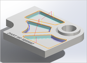 |
Profiling allows you to cut the perimeter of machining regions. In the example of the left we see a 5 degree ramp entry motion with Arc Fitting (shown in dark blue). On the right we see a finishing Profiling cut around the perimeter of the three inner pockets.
Engraving
The Engraving toolpath strategy allows you to select open or closed regions to engrave. In addition to 2D regions, 3D regions can also be chosen. Multiple depths can be specified for better control of the engraving operation. This method is especially suited for engraving text and logos onto part geometry. Unlike the 3 Axis Curve Machining methods, the cutter is not projected to the surfaces below. It merely follows the selected regions.
 |
 |
In the Engraving toolpath strategy the tool tip follows the selected curve regions. You can select from a variety cutting tool types. On the left we see text being engraved onto a part. On the right we see the cutting tool following the selected sketch regions.
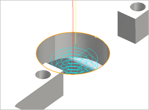
Hole Pocketing
Hole Pocketing can be used to cut larger diameter holes as a milling operation instead of drilling. The hole radius and depth can be specified, along with the number of levels. The Engagement can be specified as a helix with the height and angle or pitch. For machines capable of helix cycles, the output can be a helix cycle. For others, it can be a series of linear moves. Hole Pocketing can be used as a roughing operation by adjusting the Hole Diameter value. You can then follow with the Hole Profiling toolpath for additional roughing and/or finishing of holes.
 |
 |
On the left we see a Hole Pocketing toolpath. The helical engagement is located at the center of the hole where cutting begins. The stepover is then applied until the outer perimeter of the hole is reached. On the right we see the same toolpath with cleanup passes added at each cut level.
Hole Profiling
Hole Profiling can be used to cut circular regions where the interior of the profile needs to be cleared of all material. The hole diameter and depth can be specified. The Engagement can be specified as a helix with the height and pitch angle. Similar to Hole Pocketing, for machines capable of helix cycles, the output can be a helix cycle. For others, it can be a series of linear moves. Hole Profiling often follows a Hole Pocketing toolpath when it is used for additional roughing and/or finishing of holes.
 |
 |
On the left we see a Hole Profiling toolpath. The helical Pitch will determine the Z distance between each 360 degree motion. On the right we can see the radial entry and exit motions clearly.
More about MecSoft CAM MILL Modules
The toolpaths shown above were programmed using VisualCAM for SOLIDWORKS. The techniques here are similar for all MecSoft CAM plugins. The MecSoft CAM MILL Module is available in 5 product configurations (Express, Standard, Expert, Professional and Premium). Here are some additional details about each of the available configurations. For the complete features list, visit the products page for each platform at VisualMILL, RhinoCAM-MILL, VisualCAM-MILL for SOLIDWORKS and AlibreCAM-MILL.
- Express: This is a general purpose program tailored for hobbyists, makers and students. Ideal for getting started with CAM programming. Includes 2 & 3 axis machining methods.
- Standard: This is a general purpose machining program targeted at the general machinist. This product is ideal for the rapid-prototyping, hobby and educational markets where ease of use is a paramount requirement. Includes 2-1/2 Axis, 3 Axis and Drilling machining methods.
- Expert: Includes the Standard configuration plus 4 Axis machining strategies, advanced cut material simulation and tool holder collision detection.
- Professional: Includes the Standard and Expert configuration plus advanced 3 Axis machining strategies, 5 Axis indexed machining, machine tool simulation, graphical toolpath editing and a host of other features. Setup 4: Pocketing & Deep Drill 7
- Premium: Includes the Standard, Expert and Professional configurations plus 5 Axis simultaneous machining strategies.


