Automatic Feature Machining (AFM) is included in MecSoft’s 2018 CAM Milling plugins. Click here to learn more about our 2018 Milling products. Using AFM will allow you to program toolpaths automatically on closed polysurface (i.e., solid) models. It works in conjunction with a knowledge base of toolpaths assigned to specific feature types that are detected in your part model. This blog post will review how you can take advantage of this functionality. The information below is similar for all of our PC-based CAM Milling plugin configurations that support (AFM). For more details there are video tutorial links at the end of the post.
AFM Rocks!
To learn even more, see these AFM related blog posts:
- New Feature Machining in 2018!
- Automatic Feature Detection (AFD) Walk-Through
What AFM Will Do For You:
The following will occur when you select the Automatic Feature Machining (AFM) icon ![]() from the Features tab toolbar:
from the Features tab toolbar:
 |
1. Toolpath Mops (Machining Operations) are created from matching operations in your default AFM Knowledge Base defined in the Features section of the CAM Preferences dialog. Depending on your CAM plug-in configuration, different Orientations of features detected by Automatic Feature Detection (AFD) are considered.
Note: The orientations recognized by AFD will depend on which configuration of the software you are running. Here is how each configuration will perform AFD:
Standard (STD): Only the orientation of the default Machine Coordinate System (MCS) Z axis will be considered.
Expert (EXP): The 4 orthographic orientations normal to the rotary axis of the current machine tool definition will be considered.
Professional (PRO) & Premium (PRE): All 6 orthographic orientations (corresponding to the 6 faces of a box) will be considered.
2. Each toolpath operation is added to your Machining Job tree and then regenerated automatically.
What You Should Do First:
You will need to do the following before running the AFM command. Items 1 and 2 only need to be performed once. Items 3 and 4 are performed for each part you want to program using AFM.
1. ![]()
![]() Create and save your (AFM) Knowledge Base. Display the online help for MILL and locate the topic Create Machining KB for Milling Features and Create Machining KB for Selected Hole Feature for help with this.
Create and save your (AFM) Knowledge Base. Display the online help for MILL and locate the topic Create Machining KB for Milling Features and Create Machining KB for Selected Hole Feature for help with this.![]()
Note: Two default AFM Knowledge Base files are included with the installation and are located in the …\FeatureBasedMachiningKBs folder of the installation. These files are named DefaultAFM_INCH.vkb and DefaultAFM_MM.vkb. You can customize these knowledge bases to suit your needs.
2. ![]() Go to the Features section of the CAM Preferences dialog and select your default Automatic Feature Machining (AFM) Knowledge Base.
Go to the Features section of the CAM Preferences dialog and select your default Automatic Feature Machining (AFM) Knowledge Base.
3. You will need to perform Automatic Feature Detection (AFD) ![]() or Interactive Feature Detection (IFD)
or Interactive Feature Detection (IFD) ![]() BEFORE running the AFM command.
BEFORE running the AFM command.
NOTE: You MUST have a solid model in order to extract machining features. If you have an open surface model, you must stitch/join to close it before running the AFD or IFD commands.
4. To speed up toolpath generation time, go to the Machining section of the CAM Preferences dialog and check the box to Always generate toolpath in multiple threads. Your PC should has a multi-core processor, take advantage of this feature.
Automatic Feature Machining (AFM) Walk-Through
Here is an example of AFM being used to automatically program toolpaths for a 3D solid model:
1. ![]() The Default (AFM) Knowledge Base is defined in the Features section of the CAM Preferences dialog. In the section of the dialog named Automatic Feature Machining (AFM) Knowledge Base, select the … button, navigate and make sure the file DefaultAFM_INCH.vkb is selected. This is the default AFM Knowledge Based installed with the program (for INCH units). It is located in the …\FeatureBasedMachiningKBs folder which is located in the …\ProgramData install path where you installed your MecSoft Cam Milling plug-in. If you have created a different AFM Knowledge Base and want to use it, first make sure it is selected in this dialog.
The Default (AFM) Knowledge Base is defined in the Features section of the CAM Preferences dialog. In the section of the dialog named Automatic Feature Machining (AFM) Knowledge Base, select the … button, navigate and make sure the file DefaultAFM_INCH.vkb is selected. This is the default AFM Knowledge Based installed with the program (for INCH units). It is located in the …\FeatureBasedMachiningKBs folder which is located in the …\ProgramData install path where you installed your MecSoft Cam Milling plug-in. If you have created a different AFM Knowledge Base and want to use it, first make sure it is selected in this dialog.

2. My part is opened. It is a 3D solid model and looks like this:

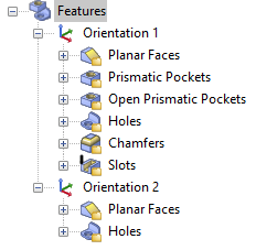
3. From the Features tab, the Automatic Feature Detection (AFD) command is selected and the following features are added to the Features tree automatically:
Note: The orientations recognized by AFD will depend on which configuration of the software you are running. Here is how each configuration will perform AFD:
Standard (STD): Only the orientation of the default Machine Coordinate System (MCS) Z axis will be considered.
Expert (EXP): The 4 orthographic orientations normal to the rotary axis of the current machine tool definition will be considered.
Professional (PRO) & Premium (PRE): All 6 orthographic orientations (corresponding to the 6 faces of a box) will be considered.
4. The part now looks like this with the Machining Features highlighted:

5. ![]() From the Features tab, the Automatic Feature Machining (AFM) command is selected and the following Machining Operations (MOps) are created, added to the Machining Job and then Generated automatically!
From the Features tab, the Automatic Feature Machining (AFM) command is selected and the following Machining Operations (MOps) are created, added to the Machining Job and then Generated automatically!

Then the AFM icon is selected and Machining Operations (MOps) from the AFM Knowledge Base are assigned to each feature and each MOp is generated automatically.
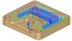
6. The following toolpaths are generated automatically for my 3D solid model:
 |
 |
 |
 |
 |
 |
More about Feature Machining
1. To learn more about what you can do with Feature Machining, visit the online help supplied with your program.![]()
2. Take moment to watch the following free video tutorials:
 What’s New in 2018 Webinar Replay What’s New in 2018 Webinar Replay |
 RhinoCAM 2018 Automatic Feature RhinoCAM 2018 Automatic FeatureMachining (AFM) Quick Start |


