 In Part 1 of this tutorial we showed you how the Create Puffed Volume command in MecSoft’s VisualART module was used to transform Doug McIntosh’s 2D drawing of the Hancock Central School’s Bulldog mascot into a 3D mesh that is suitable for machining. In Part 2 below we show you how the VisualCAD/CAM MILL module is used to create toolpath strategies to machine the part.
Note: This is not a step by step tutorial. This 2-part tutorial teaches you the workflows between the MecSoft CAM ART and MILL modules that were used to complete this project. We recommend that you first become familiar with both modules so that you can better leverage this tutorial into your workflow. Quick Start tutorials are available for both the ART and the MILL modules. See Get your Free 2020 Resource Guides! to gain quick access to these guides. |
- ART-MILL Workflow Part 1: Raising the HCS Bulldog with VisualART!
- The CAD Model
- The HCH Bulldog MILL Setup
- Rough & Finish Toolpaths (3 Axis)
- Detailing Toolpaths (2½ Axis)
- The Predator in Sand Cast Aluminum
- More about the Hancock Central School Bulldogs
- Reference Articles
![]() In this project from Doug McIntosh, volunteer instructor at Hancock Central School (HCS) in Hancock MI, a plaque of the HCS Bulldog mascot is first machined in wood and then in aluminum from stock measuring 8” x 8” x 5/8”. This aluminum core is then used to press a hollow cavity into sand that has been treated with a strength bonding agent. This is one of many projects students at HCS can use to learn about CNC and sand casting in the school’s complete onsite metal working foundry. Click here to learn more about the sand casting process.
In this project from Doug McIntosh, volunteer instructor at Hancock Central School (HCS) in Hancock MI, a plaque of the HCS Bulldog mascot is first machined in wood and then in aluminum from stock measuring 8” x 8” x 5/8”. This aluminum core is then used to press a hollow cavity into sand that has been treated with a strength bonding agent. This is one of many projects students at HCS can use to learn about CNC and sand casting in the school’s complete onsite metal working foundry. Click here to learn more about the sand casting process.
The CAD Model
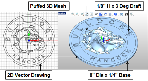
The geometry used to generate these toolpaths includes 2D curves and 3D meshes. Some of the curves were used in the ART module to create the 3D HCS Bulldog mesh. Others were drawn to help contain the toolpath operations as you will see below. Additional mesh geometry was modeled in VisualCAD including the cylindrical base and the raised lettering. The geometry is illustrated below. See ART-MILL Workflow Part 1: Raising the HCS Bulldog with VisualART! to learn more about how the HCS Bulldog 2D drawing was created in VisualCAD.
 |
|
| (Left) The HCH Bulldog logo starts out as a 2D vector drawing in VisualCAD. | (Right) The 3D plaque geometry consists of a raised HCH Bulldog mesh & extruded base and letters. |
The HCS Bulldog MILL Setup
Once the 2D and 3D geometry is created we can proceed to the MILL module where toolpaths are created and the G-Code posted that will run the CNC machine at Hancock Central School. In the left side image below we see the resulting cut material simulation of all toolpaths in the HCH Bulldog Machining Job. On the right we see the Machining Job tree with each toolpath strategy listed in the order it is performed. The Work Zero (i.e., machine zero) is located at the top center of the stock geometry.
 |
 |
Rough & Finish Toolpaths (3 Axis)
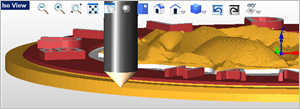
The machining job begins with two 3 Axis Horizontal Roughing toolpath strategies to remove excess stock material. The first removes material from the top of the stock down to the top of the lettering using a ¼” diameter flat end mill. This toolpath is contained to the outer perimeter diameter of the base of the plaque. Step Minimization is enabled allowing the single toolpath to serve as both a roughing and then a re-roughing operation. The toolpath and cut material simulation is shown below.
 The 3 Axis Horizontal Roughing toolpath is displayed and is contained to the diameter of the base. |
 The cut material simulation for the 3 Axis Horizontal Roughing toolpath is shown in multiple cut levels. |
The second 3 Axis Horizontal Roughing toolpath begins at the top of the lettering and ends at the bottom of the lettering and uses a ⅛” diameter x 3 degree taper or “Vee” mill. The toolpath is also contained between two concentric 2D circles that lie on the XY plane. Refer to The CAD Model section above for the location of the geometry. Each letter is located between these two concentric circles. This operation removes a total of ⅛” of material in Z. With a stock allowance of zero, this is considered the finishing operation for the lettering.
This project is illustrated using the VisualCAD/CAM Standard configuration. In the Professional configuration this second Roughing toolpath can be replaced with the 3 Axis Horizontal Re-Roughing toolpath that calculates the required stock to remove from the previous cut material simulation, saving some machining time. |
 The second Horizontal Roughing toolpath is contained between two concentric circles that lie on the XY plane. |
 The cut material simulation for the second Roughing operation is shown in Red. The first Roughing operation is shown in White. |
The third operation in the Machining Job is referred to as 3 Axis Spiral Machining. It is one continuous toolpath motion that begins at the center of the Bulldog and spirals outward by an offset distance that is 50% of the cutting tool diameter. The outer perimeter curve of the Bulldog is used as containment for this operation. The cutting path is shown in the left side image below. The resulting cut material simulation is shown on the right.
 The 3D Bulldog mesh is machined using a 3 Axis continuous Spiral toolpath. |
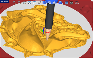 The cut material simulation for the 3 Axis Spiral Finishing toolpath is shown. |
Detailing Toolpaths (2½ Axis)
The remaining toolpaths in the Machining Job tree consists of 2½ Axis Profiling, Pocketing and Chamfering operations. The first Profile cuts the outer perimeter in two levels. The second Profile cuts the outer shelf in one level and two stepover passes. The Pocketing operation cuts between the outer perimeter of the Bulldog and the inner circle perimeter of the lettering. The last four operations in the Machining Job tree are 45 degree Chamfer toolpaths. These include the upper outer perimeter, the inner and outer lettering diameters and the outer perimeter of the Bulldog. These detailing operations are shown in the images below.
 2½ Axis Profiling and Pocketing toolpath operations are used for finish detailing. |
 2½ Axis by 45 degree Chamfer operations are used to detail break the sharp edges shown. |
The Nashville Predators® in Sand Cast Aluminum
 Similar to the HCS Bulldog plaque, this project begins with a VisualCAD drawing representing the Nashville Predators® emblem outline and detail curves drawn in the top view using a background image as a template, as well as additional perimeter and containment curves. The geometry is shown in the left side image below. All are 2D curves that lie at Z0 on the XY plane. The predator border and detail curves were then “Puffed” up to create a 3D mesh in VisualART. The additional extruded diameter base and raised lettering were modeled in VisualCAD.

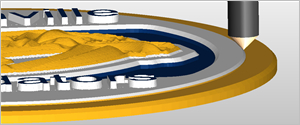
Similar to the HCS Bulldog, the Machining Job tree and resulting cut material simulations are shown below. Beginning with a 8” x 8” x ½” stock material, 3 Axis Horizontal Roughing, 3 Axis Parallel Finishing and 2½ Axis Profiling and Chamfering toolpath strategies are used. The Work Zero (i.e., machine zero) is located at the top center of the stock geometry. Again, the emblem is first cut in cherry wood as a proof of concept. It is then cut in aluminum. The aluminum emblem is then used to impress a cavity into the treated casting sand. This cavity is then poured with molten aluminum in the school’s foundry..
You may be wondering how the custom coloring was applied to the cut material simulations shown in this tutorial. From the Machining Job tree, right-click on an operation and select Properties to assign a color to that operation. Then from the bottom right corner of the Simulate tab set the Simulation Display State dropdown menu to MOp and then simulate all operations in Machining Job. |
 |
 |

More about the Hancock Central School Bulldogs
![]()
Hancock is a city in Houghton County in the U.S. state of Michigan. It is located across the Keweenaw Waterway from the city of Houghton on the Keweenaw Peninsula. The city has been consistently ranked as the third-snowiest city in the United States. The Hancock Public Schools was created to serve the descendants of the hardworking immigrants who worked the mines in the area. The Bulldog pride in the Hancock community stems from the values of this diverse community. To learn more about Hancock Central High School we invite you to visit them online here.
References
- VisualCAD/CAM at Hancock Central School
- ART-MILL Workflow Tutorial Part 1: Raising the HCS Bulldog with VisualART!
- Learn more about VisualCAD/CAM-ART (VisualART)
- Learn more about VisualCAD/CAM-MILL (VisualMILL)
- Learn more about VisualCAD


